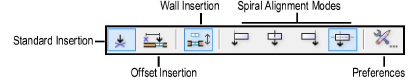
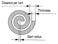
The Spiral tool draws an Archimedes spiral. The number of turns, distance per turn, start radius and thickness can be specified, as well as the number of points used to define the curve. Use the alignment modes on the Tool bar to temporarily override the insertion point. These modes change the alignment of the insertion point along the X axis of the bounding box surrounding the spiral.
Spiral Alignment Mode |
Description |
Align Object Left |
Moves the insertion point to the left edge of the spiral’s bounding box, along the original X axis |
Align Object Center |
Moves the insertion point to the center of the spiral’s bounding box, along the original X axis |
Align Object Right |
Moves the insertion point to the right edge of the spiral’s bounding box, along the original X axis |
Align Object Origin |
Leaves the insertion point at the actual or original position |
For information on using the Offset Insertion and Wall Insertion modes, see Offset Symbol Insertion Mode and Wall Insertion Mode.

To draw a spiral:
1. Click the Spiral tool from the Basic palette.
2. Select the insertion type and alignment from the Tool bar.
3. Click to define the center of the spiral.
If this is the first time a spiral is placed in this session, the Spiral Properties dialog box opens. These parameters apply to subsequently created spirals; they can be changed later by accessing them from the Object Info palette.
4. Specify the spiral properties.
Click to show/hide the parameters.
5. Click OK.
A spiral with the specified parameters is placed on the drawing.
To create a 3D spiral, see Creating Helix-Spirals.
Click here for a video tip on this topic (Internet access required).
![]()