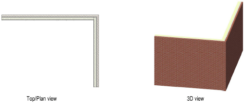
The Wall tool creates a hybrid wall object, simultaneously adding both a 2D and a 3D version of the wall to the drawing. Walls can be drawn in Top/Plan or in a 3D view. Standard walls or curtain walls (Vectorworks Design Series required) can be created.
Create walls by drawing them with the mouse, or by using a mouse-Data bar combination (see Using the Data Bar). The following directions assume that the walls are drawn with the mouse.
If walls are drawn using the Data bar, the Control Line mode setting determines whether the dimensions entered are for the left, center, or right edge of the wall, or a custom location.

To create straight walls:
Select the Wall tool from the appropriate tool set:
● Fundamentals workspace: Walls tool set
● Design Series workspaces: Building Shell tool set
● Landmark workspace: Site Planning tool set
Click the desired Control Line mode, and click either Polygon or Rectangle mode (see Creating Walls).
Do one of the following:
● In Vectorworks Design Series products, to use an existing wall style from the resource libraries, click Wall Style on the Tool bar. From the Resource Selector, double-click a resource to activate it. Or, to draw an unstyled wall, leave the <Unstyled> setting as is. Proceed to step 4.
● To create a custom wall style, click Preferences from the Tool bar. From the Wall Preferences dialog box, set the default properties and click OK. The properties can be edited from the Object Info palette.
Click to show/hide the parameters.
The Wall Attributes dialog box opens. The wall attributes of an unstyled wall are initially set to the parameters displayed in the Attributes palette. If they are changed here, the Attributes palette reflects the changed attributes of the selected wall (after exiting the Wall Preferences dialog box).
Fill, pen, drop shadow, and opacity can be set by class rather than by the attributes in the Wall Attributes dialog box. If the wall class is changed later, the wall changes to use the attributes of the new class. Wall attributes cannot be overridden on a per-instance basis; if a wall style uses class attributes, all walls of that style must use class attributes. However, walls of the same wall style can be placed in different classes.
Click to show/hide the parameters.
Click OK to return to the Wall Preferences dialog box. If components are to be added to the wall, click New to define each component (see Creating Wall Components). The Overall Thickness is then defined by the thickness of the wall components.
In the Vectorworks Design Series products, wall components can be assigned to a class; this allows maximum flexibility since the component classes can be shown or hidden separately from the wall class. To control appearance and visibility, select a class from the list of classes present in the drawing, or create a new class. Select <Object Class> to place the component attributes in the same class as the wall object. By default, components are assigned to the wall class.
In the Vectorworks Fundamentals product, wall components are automatically assigned to the <Object Class> and are always in the same class as the wall.
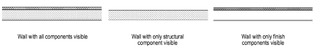
When a component is in an invisible class, its fill and lines are hidden. Invisible components on the interior and exterior of a wall cause the wall’s lines and fill to adjust to the visible components only, making the wall appear thinner than its actual width. This allows walls to show only their structural components, for example. If all components are invisible, the wall displays at its full thickness, without components.
The Hide Details preference can be used to hide wall components based on scale (Vectorworks Design Series required); see Hiding Wall Components.
Click the Insertion Options tab to set the wall insertion options.
Curtain walls have slightly different parameters; see Creating Curtain Walls.
Click to show/hide the parameters.
Click the Textures tab to select textures for the wall parts.
Textures for curtain walls are controlled by the frame and panel settings on the Definition tab; see Creating Curtain Walls.
Click to show/hide the parameters.
Click the Data tab to specify wall record information, which is also the IFC data that can be assigned when creating an IFC entity (edits to either the Data tab or the IFC entity edit the data in both locations). This information can be included in a wall style schedule (Vectorworks Design Series required). These fields are optional; enter text only where desired.
When the wall parameters have been specified, and any changes have been saved as a wall style resource if desired (Vectorworks Design Series required), click OK.
In the Design Series, a saved or selected wall style is saved as a resource in the file, and displays in the Resource Manager and in the Wall Style list on the Tool bar. See Creating Wall Styles.
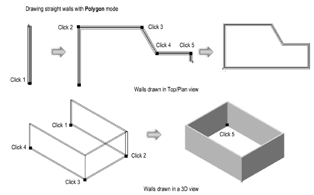
If Polygon mode is selected, click at the starting point of the first wall section.
Click to end the first wall section.
To continue creating walls, click at the end of each additional wall section.
Double-click to finish the wall if the start point and end point are not at the same location; otherwise, click at the starting location (a SmartCursor cue displays) to finish the wall.
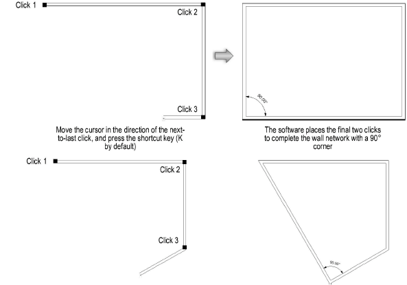
Alternatively, after completing all but the final click, press the keyboard shortcut (K by default) to automatically close the polygonal wall network. See Modifying Special Shortcuts to change the shortcut.
When drawing a wall network, move the cursor in the direction of the next-to-last click but press the shortcut key instead of clicking; the software extrapolates the correct alignment and position for a 90° corner and places the final two clicks to complete the wall network.
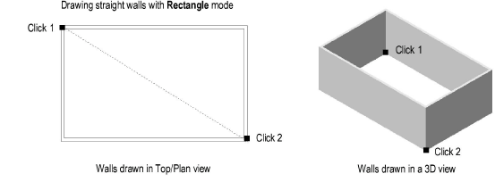
If Rectangle mode is selected, click at the wall’s start point; this becomes one corner of the rectangular wall system. Move the cursor to the opposite corner until the desired size is previewed.
Click to set a corner point on the wall system. Four walls are created.
When the Vectorworks preference Auto join walls is on, walls drawn in Rectangle mode that overlap or touch each other interact, so complex wall systems can be drawn quickly. See Automatically Joining Walls in Rectangle Mode for the rules that define these interactions.
The properties of a wall can be edited from the Object Info palette; see Wall Properties.
~~~~~~~~~~~~~~~~~~~~~~~~~
![]()