The scene file contains the geometry that represents fixtures, trusses, pipes, set pieces, venue walls, and so on. The Scene window displays the scene file, and it is also where visualization occurs.
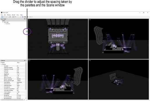
Drag the divider along the edges of the Scene window to adjust the amount of space taken up by the Scene window and any open palettes.
The Scene window can be viewed as a single viewport, or as four viewports, each with a different view.
To toggle the number of viewports in the Scene window:
Select Window > Toggle Number of Viewports, or press the M key.
The Toggle Fullscreen command toggles between a maximized full screen of the bottom right viewport and the normal, resizable display of the Vision program.
To switch to full screen view:
Select Window > Toggle Fullscreen, or press the Ctrl+Shift+F (Windows) or Cmd+Shift+F (Mac) keyboard shortcut.
The bottom right viewport expands, filling the entire screen.
To exit full screen view, press the Esc key, or press the keyboard shortcut again.
Vision uses a sophisticated process to realistically replicate the behavior of the human eye. Following an exposure to bright lighting, the eye gradually recovers its sensitivity once in the dark. It takes some time for the eye to adapt before it can adequately see objects in the new, lower light level.
Luminance adaptation is simulated within Vision. For example, when a blackout occurs, the ambient lighting level automatically adjusts after a period of time to realistically replicate the reaction of a human eye viewing the scene. Conversely, the ambient level appears to dim when bright lighting is enabled within the scene.
The ambient light level and exposure can be adjusted manually using keyboard shortcuts or by modifying the ambient setting in the ROOT (global) portion of the Properties window; see Selecting Global Scene Parameters, Objects, and Fixtures.
To increase the ambient light level by 1 with keyboard shortcuts, press Ctrl+Shift+L (Windows) or Cmd+Shift+L (Mac); to decrease the ambient light level by 1, press Ctrl+Shift+K (Windows) or Cmd+Shift+K (Mac).
To simulate the use of house lights, press Ctrl+Shift+J (Windows) or Cmd+Shift+J (Mac) to toggle them on and off. If the ambient setting in the global properties is less than 50, the toggle increases the ambient setting by 50. If the ambient setting is 50 or more, the toggle decreases the ambient setting by 50.
Each viewport in the Scene window includes a Looked At point, which is an RGB indicator of the camera’s looked at position. The indicator helps with rotation and panning. Toggle the indicator on and off with the Window > Toggle Looked At command, or press the Ctrl+Shift+O (Windows) or Cmd+Shift+O (Mac) keyboard shortcut.
Each viewport in the Scene window can display in one of ten preset views, or in a custom view that can be saved (see Saving User Views). The label in the top left corner of the viewport indicates the current view; “User” designates either a custom view or one of the isometric preset views.
The six standard preset views can be accessed from the viewport context menu; right-click on the viewport and select one of the views from the context menu. Alternatively, use the shortcut keys on the numeric keypad to access the standard views as well as isometric views. Isometric views are labeled as User views.
► Click to show/hide the parameters.
The Tool bar includes additional ways of adjusting the viewports in the Scene window.
The Orbit camera tool adjusts to a custom view, simulating movement over and around a real-world model. The center of rotation is the viewport center.

To adjust the view of a viewport:
Click the Orbit camera tool from the Tool bar, or press Shift+C.
Within the viewport, click and drag in the direction of movement while you hold down the mouse button.
The viewport label displays “User,” since the view is a custom view and not one of the preset views.
The Orbit camera tool can be used in boomerang mode if you have a center mouse button. Hold down Ctrl+center mouse button (Windows) or Cmd+center mouse button (Mac) to temporarily pause the current tool and switch to the Orbit camera tool. Release the buttons to return to the previous tool.
The Zoom tool controls how close or far away objects appear in the viewport. Zoom in to get a close-up view of a detail, and zoom out to get a broader view of the scene.

To zoom in or out of a viewport:
Click the Zoom tool from the Tool bar, or press the C key.
Within the viewport, click and drag while you hold down the mouse button. Move the cursor up to zoom in on the viewport, or move the cursor down to zoom out of the viewport.
On a wheel-mouse, roll the mouse wheel forward to zoom in on the viewport (the Zoom tool does not need to be selected). Roll the mouse wheel backward to zoom out from the viewport.
This feature will not work properly if standard scrolling is disabled in the mouse setup. For example, if the mouse’s scrolling size is set to “none,” mouse zooming in Vision is disabled. (The specific settings required for this feature depend on the type of mouse being used.)
Use the Pan camera tool to move the scene around in the viewport, changing the area of display.

To pan within the viewport:
Click the Pan camera tool from the Tool bar, or press the H key.
Alternatively, depending on the type of mouse being used, press and hold the center mouse button to pan.
Within the viewport, click and hold down the mouse button, and drag to move the scene.
The Pan camera tool can be used in boomerang mode. Hold down the Space bar or the center mouse button, if you have one, to temporarily pause the current tool and switch to the Pan camera tool. Release the Space bar or button to return to the previous tool.
Use the Fit objects in view tool to change the view to zoom to the selected objects. When the Scene window displays four viewports, this tool applies only to the bottom right viewport.

To fit the view to objects:
Select one or more objects from the Scene Graph palette. To fit the zoom level to all objects in the Scene window, select ROOT from the Scene Graph palette.
Click the Fit objects in view tool from the Tool bar.
The zoom level adjusts to the selected objects.
Each viewport can also display as solid or wireframe, and in orthographic or perspective projection.
To set the rendering and projection of a viewport:
Right-click on the viewport and select one of the commands from the context menu:
● Wireframe
● Solid
● Orthographic
● Perspective
A custom view (labeled “User”) can be saved and restored later. Up to ten Scene window views can be saved. The views are saved with the file. Use the keyboard numbers for these operations; do not use the numeric keypad.
To save a view:
Click the viewport with the view to save, so that it has the focus.
Click the Ctrl (Windows) or Cmd (Mac) key, and any number key (1–9) on the keyboard.
The current viewport view settings are saved to the keyboard shortcut.
To restore a view:
Press the desired keyboard number key (1–9) to restore the saved view.
~~~~~~~~~~~~~~~~~~~~~~~~~