Presenting the project
Viewports can display entire, as well as cropped, views of a drawing, with specified layer and class visibility settings, projection, render mode, and orientation parameters (complete with details, annotations, dimensions, and title block borders). Viewports can show other parts of the active document, or even portions of other documents. If the drawing changes, update the viewports to reflect the changes.

There are several different types of viewports, depending on whether you have the Vectorworks Fundamentals product or one or more Vectorworks Design Series products.
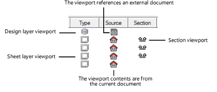
In both the Vectorworks Fundamentals and Vectorworks Design Series products, you can create one or more viewports on a sheet layer, and each viewport can show one or more design layers from this document. Sheet layer viewports, often created for presentation purposes, are created on special layers called sheet layers. Sheet layers retain their own print settings, including print area, resolution, and printer setup parameters. For more information on sheet layers, see Creating layers. A sheet layer viewport can also be created from a clip cube or be linked to a Renderworks camera.
Vectorworks Design Series products allow you to create one or more viewports on a design layer, and the design layers shown in the viewports can be either from the current document, or referenced from another document. Like a sheet layer viewport, a design layer viewport can display design layers from the current file in a full or cropped view; unlike a sheet layer viewport, it can include one or more design layers that are referenced from another file.
A vertical or horizontal section viewport creates a cross section view of a model at a defined cut plane, but leaves the model intact. A section viewport can be created from a design layer, another non-sectioned viewport, a clip cube on a design layer, or (for vertical section viewports) from a section line or section-elevation marker in the drawing. It can be placed on a design layer or sheet layer. Section viewports let you choose whether to view objects before and beyond the cut plane or above and below the cut plane, and to set different display options and attributes for 3D objects by class or individually.
Interior elevation viewports are section viewports that allow you to simultaneously create as many as four interior elevation viewports from a selected room or area of the model. An interior-elevation marker automatically placed on the design layer allows you to edit which views you display and maintains coordination between the drawing and the viewports. These viewports can be placed on either a design layer or a sheet layer.
A detail viewport is a cropped sheet layer viewport that shows a detail view of any part of a drawing. A detail viewport can be created from a design layer, another sheet layer viewport, or a section viewport. The crop object used to create the detail viewport becomes a callout object that is linked to the detail viewport for easy navigation between layers.
The Viewports tab of the Organization dialog box differentiates among the various types of viewports.

|
|
Click here for a video tip about this topic (internet access required). |
~~~~~~~~~~~~~~~~~~~~~~~~~