SprocketsSprockets
Click the Sprocket tool from the Machine Components tool set.
Click to place the object in the drawing, and click again to set the rotation.
The first time you use the tool in a file, a properties dialog box opens. Set the default properties, and click OK. The properties can be edited from the Object Info palette.
Click to show/hide the parameters.
Parameter |
Description |
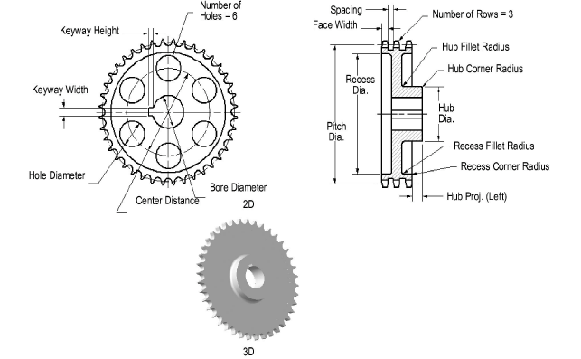
Std. Chain No. (Pitch) |
Select the standard ANSI or ISO roller chain number; the pitch is given as reference |
Number of Teeth |
Enter the number of teeth |
Pitch Diameter (Ref.) |
Displays the pitch diameter based on the pitch and number of teeth |
Number of Rows |
Enter the number of rows of teeth |
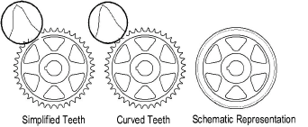
Tooth Profile |
Select the type of tooth profile
|
Use Standard Width and Spacing |
Select to use standard Face Width and Spacing values based on the selected Pitch; deselect to specify custom values and enter the values |
Face Width |
Enter the face width value |
Spacing |
Enter the spacing between rows of teeth |
Draw Recess (2D only) |
Select Draw Recess to draw a recessed web, and specify the 2D parameters |
Web Thickness |
Enter the web thickness |
Recess Diameter |
Enter the recess diameter |
Recess Corner Radius |
Specify the recess corner radius |
Recess Fillet Radius |
Specify the recess fillet radius |
Draw Hub (2D only) |
Select to include a hub and then specify the 2D parameters |
Hub Diameter |
Enter the hub diameter |
Hub
Projection |
Specify the amount of projection for the hub on both the left and the right; a negative value indicates that the hub face is recessed |
Hub Corner Radius |
Enter the hub corner radius |
Hub Fillet Radius |
Enter the hub fillet radius |
Draw Bore (2D only) |
Select to draw a bore and then specify the 2D parameters |
Bore Diameter |
Enter the bore diameter |
Keyway |
If a keyway is present, select the square, rectangular, or custom size; otherwise, select None. The square and rectangular selections apply the ASME-recommended size based on the bore diameter. |
Width/Height |
For custom keyway sizes, enter the width and height values of the keyway |
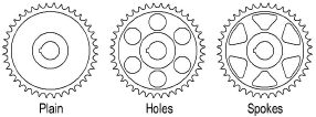
Web Configuration (2D only) |
Select the web configuration and then specify the 2D parameters, if any. When Holes are selected, their size can be specified as a percentage or diameter value.
|
Number |
Indicate the number of holes or spokes for the sprocket (does not apply to Plain web configurations) |
Size (10 - 100%) |
For Holes (Percent) and Spokes web configurations, enter the percentage of the recess opening occupied by the holes or spokes |
Center Distance |
When Holes is selected for the web configuration, specify the distance between the hole centers |
Hole Diameter (2D and 3D) |
When Holes is selected for the web configuration, indicate the size of the holes |
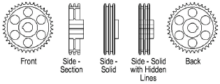
View (2D only) |
Select the 2D view
|
Draw Center Lines (2D only) |
Select to draw the sprocket with center lines |
![]()