In Vectorworks, you can create 2D and 3D objects. Symbols, which are converted objects, can also consist of 2D, 3D, or hybrid objects.
In addition, there are special symbol categories which indicate the symbol’s behavior at placement. These categories are color-coded within the Resource Browser for identification. The category a symbol belongs to depends on the type of object converted to a symbol and the options selected at symbol creation.
Symbols can be nested within other symbols.
Symbol Type |
Symbol Category |
|
2D |
2D symbols are composed exclusively of 2D screen plane objects. The instances of the symbol are considered planar, and may occupy the screen plane, layer plane, or a 3D plane. |
|
3D |
3D symbols are created from 2D planar objects and/or 3D objects, have a height (Z coordinate) as well as widths and lengths (X and Y coordinates). These objects display flat in Top/Plan view. However, they retain their 3D properties. Symbols created from 3D objects that are not hybrid objects appear flat in 2D views, but show dimension in 3D views. |
|
Hybrid |
A hybrid symbol contains both a 2D screen plane object and a 3D component, and displays correctly according to the view. The advantage of working with hybrid symbols is that 3D models can automatically be created from 2D drawings, or vice versa. For example, a hybrid door symbol displays as a “swing arc” in Top/Plan 2D view and as a fully formed door in a 3D view. Hybrid symbols must be inserted in the layer plane. |
|
Black |
This is the most common type of symbol, the static symbol. Its parameters are saved within the symbol definition, and set at placement. Changes made to the symbol definition affect all instances of the symbol. |
|
Blue |
When placed, this type of symbol is converted to a group. Any changes made to the symbol definition later have no effect on the group. At symbol creation, select Convert to Group in the insertion options to specify a “blue” symbol. |
|
Red |
When placed, this type of symbol is converted to a plug-in object. It has a specific insertion behavior (point, linear, rectangular, or path) and set parameters, and it can be modified, with many variations of the same object in the file. At symbol creation, select Convert to Plug-in Object in the insertion options to specify a “red” symbol. Changes to a “red” symbol definition affect future instances, but not existing ones. |
|
Green |
This is a page-based symbol. Typically these symbols are annotation symbols that are scaled relative to the page size, such as a North arrow indicator. |
Plug-in objects have all the power of standard symbols, with the added advantage of being customizable. Unlike symbols, plug-in objects have the option of being placed onto the drawing and remaining modifiable. This is useful if the drawing needs to contain many different variations of the same object.
Some tool sets and libraries contain plug-in objects; for example, the Scale Bar tool, located in the Dims/Notes tool set, inserts a plug-in object. In addition to the tool sets, pre-defined plug-in objects are available in the Libraries folder (in subfolders beginning with the word Object or Objects), and are accessed through the Resource Browser.
When a plug-in object from a tool set is inserted, an object properties dialog box may open the first time the item is placed in the drawing. The properties in this dialog box set the default values for the object for this file. Modify the properties prior to inserting the object, or accept the default values and click OK. Object instances can be modified through the Object Info palette after insertion.
Custom plug-in objects can be created through the Tools > Plug-ins > Plug-in Manager; see Creating Scripted Plug-Ins.
In addition, a symbol can be saved as a “red” symbol that becomes a plug-in object upon insertion.
There are four different types of plug-in objects: point, linear, rectangular, and path. Each type is different in how it is placed in the drawing and edited.
Linear and rectangular objects cannot be inserted directly into a wall. However, once placed in the drawing, they can be dragged onto a wall to insert them.
Point plug-in objects are placed by a single click in the drawing to specify the location, and then a second click to set the rotation angle. This is the same way symbols are placed using the symbol insertion tool. A preview image of the object is visible at the cursor location. Point plug-in objects cannot be edited (resized or rotated) with the cursor; they are edited using the Object Info palette.
Linear plug-in objects are placed with two clicks. The first click sets the beginning point and the second sets the endpoint of a line. The orientation of the object is determined by this line. The object can be resized or rotated by clicking on a reshape handle at either end of the line. It can also be edited using the Object Info palette.
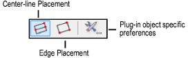
Rectangular plug-in objects are placed by a sequence of three clicks in the drawing. There are two different placement modes which determine how these three clicks are interpreted.
● Center-line Placement mode: The first click specifies the origin of the object, the second click specifies the length, and the third click defines half the width of the rectangular object. After the second click, the cursor displays feedback symmetrically on both sides of the center-line of the rectangle.
● Edge Placement mode: The first click specifies one corner of the rectangular object, the second click determines the length, and the third click specifies the entire width.
When a rectangular plug-in object is selected, there are eight selection handles visible. The object can be resized by dragging these handles, or edited through the Object Info palette.
Path plug-in objects are created with a sequence of several clicks that define the vertex points along a path. There are two different types of path plug-in objects based on the type of path that is used. A 2D path plug-in object uses a polyline path and a 3D path plug-in object uses a 3D NURBS curve for its path.
Path plug-in objects can be edited using the Reshape tool directly. They can also be edited through Modify > Edit Group, or the Object Info palette.
~~~~~~~~~~~~~~~~~~~~~~~~~
![]()