 Assigning
IFC Data to ObjectsAssigning
IFC Data to Objects
Assigning
IFC Data to ObjectsAssigning
IFC Data to ObjectsWhen a building project is exported to an IFC file, Vectorworks plug-in objects and pre-assigned symbols are automatically assigned to IFC entities. Simple hybrid or 3D geometric objects, unless they receive IFC assignments, are not exported. To be exported, these object associations must be made prior to export with the IFC Data command. IFC data can also be included or excluded from export with the IFC Data Mappings command.
Assigning IFC data to an object does not alter it in any visible way. The object can still be edited with standard Vectorworks tools and commands. An example of this would be to use a floor or slab object to model a flat ceiling. Select the floor or slab in the model, and then select the IFC Data command. From the list in the Select IFC Object dialog box, select IfcCovering, the correct assignment for a ceiling. Then, in the IFC Data dialog box, select CEILING from the PredefinedType list in the Properties for the selected Data Set lists.
The IFC Zones, Systems and Groups command attaches IFC data to space zones, systems, or groups. See Assigning IFC Data to Zones, Systems, and Groups.
An object can also be “wrapped” in a container so that it is identified in the Vectorworks file as an IFC Entity object. Editing an IFC Entity is less direct than editing simple Vectorworks objects with IFC data attached. For this reason, an IFC Entity can be useful for model elements that need to be secured from casual changes.
To assign IFC data:
Select the object, group, symbol instance, or symbol definition for assignment of IFC data. More than one item can be selected at one time.
IFC data applied to symbol instances affect only the selected instances, not all instances. To attach IFC data to a symbol definition, locate the symbol definition in the Resource Manager. Right-click (Windows) or Ctrl-click (Mac) the symbol and select IFC Data from the context menu. This attaches the IFC data to future symbol placements, and to any current instances that do not have IFC data already attached to them.
Select the IFC Data command from the appropriate menu:
● Architect workspace: AEC > IFC Data
● Landmark workspace: Landmark > Architectural > IFC Data
● Spotlight workspace: Spotlight > Architectural > IFC Data
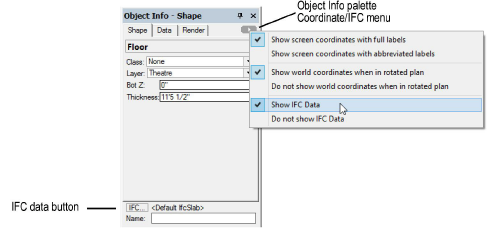
Alternatively, select Show IFC Data from the Coordinate/IFC menu on the Object Info palette to enable IFC-related information display on the palette, and then click IFC from the bottom of the Object Info palette.
The Select IFC Object dialog box opens, listing available IFC object types.
Click to show/hide the parameters.
The IFC Data dialog box opens.
The property sets of objects with IFC data and IFC entities can be mapped and saved in mapped configurations as described in Managing IFC Data Mapping; use the assigned mapping by selecting the “by style” data mapping option, or specify mapping for the instance by selecting “by instance” for the data set property.
Click to show/hide the parameters.
Click OK to assign the IFC data to the object, or create the IFC entity. The Object Info palette displays the selected IFC object or entity information (IFC value type and the object name, if any) when Show IFC Data is enabled on the palette. Objects like walls and slabs, with default IFC data assigned, display with <Default> to indicate that the default IFC data have not been modified.
The geometry of IFC entities can be edited with the Modify > Edit IFC Entity command; alternatively, right-click (Windows) or Ctrl-click (Macintosh) on the IFC entity and select Edit from the context menu.
~~~~~~~~~~~~~~~~~~~~~~~~~
![]()