A fillet, chamfer, or shell object follows certain editing conventions.
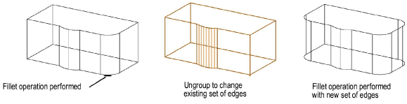
The set of edges or faces used to create the fillet/chamfer or shell cannot be changed once the operation is performed; edges or faces cannot be deleted from or added to the existing set. To add or delete edges or faces, first ungroup the object, and then perform the operation again.
The properties that can be changed from the Object Info palette include the thickness of a shell, direction of shelling (inside/outside), the radius of a fillet or setback distance of a chamfer. In the case of variable radius fillets, the percentage of length and radius value at each point can be edited. However, only the parameters of the topmost object can be changed.
For example, if a shell is created, and then some of the shell edges are filleted, only the fillet parameters can be changed directly from the Object Info palette. To change the shell thickness, the fillet object must first be ungrouped. To change the original extrusion, both the fillet and the shell must be ungrouped. Once changes have been made, reapply the shell and fillet.
The Modify > Edit Group command cannot be used for these objects.
Click here for a video tip about this topic (internet access required).
~~~~~~~~~~~~~~~~~~~~~~~~~
![]()