Section
Lines and Section-Elevation MarkersSection
Lines and Section-Elevation Markers
Section
Lines and Section-Elevation MarkersSection
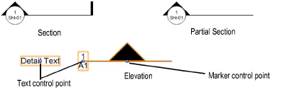
Lines and Section-Elevation MarkersSection lines and section-elevation markers look very similar on a drawing, but they are created differently.
A section line is automatically created when a vertical section viewport is created (horizontal sections do not have them). The section line graphically indicates the cutting plane of the section viewport and shows the orientation of the section view. Specify the graphic properties of the section line (such as the marker style), when you create the section viewport. To access a section line from its section viewport, click Section Line Instances from the Object Info palette (see Section Line Instances).
A section line that has been pasted from a copy, duplicated, or mirrored from a section line that is associated with a section viewport becomes an “unlinked” section line. It displays with black and yellow stripes and the Section Viewport field in the Object Info palette displays “Not Linked.”
A section-elevation marker is graphically similar to a section line, but it is not necessarily linked to a viewport. Use the Section-Elevation Marker tool from the Dims/Notes tool set to insert a marker, as a reference line graphic for sections and elevations, or as a cutting plane graphic. Select Preferences from the Tool bar to specify the graphic properties of the object before you create it.
A section-elevation marker can be linked to a viewport. Depending on the type of viewport it is linked to, its drawing number and sheet number are synced to the selected viewport, similar to a section line. Section-elevation markers that are linked to a viewport display with a green link icon next to the beginning maker. The linked section-elevation marker can have different graphic properties from a section line that is also associated with a section viewport.
When a section viewport is deleted, the associated section line and any linked section-elevation markers are also deleted.

To insert a section-elevation marker:
Select the Section-Elevation Marker tool from the Dims/Notes tool set.
Click Preferences from the Tool bar, and set the default parameters for section-elevation markers.
Click to place one end of the section-elevation marker.
To insert a single-segment marker, drag to determine the marker length.
To insert a multi-segment marker, click to define each segment. Because a multi-segment marker is a polyline, the methods of drawing and editing polylines apply (see Creating Polylines).
Double-click to finish placing the section-elevation marker.
After creation, edit section lines and section-elevation markers as follows:
● Use the Object Info palette to edit the graphic properties (such as the marker style).
● Use the Attributes palette to apply attributes (such as the fill or pen color).
● Use options on the Text menu to control the text appearance (such as the font or size), or assign a text style.
● Use the Selection or Reshape tool to edit the objects (see Modifying Section Lines Graphically).
● A section-elevation marker can be linked to a viewport by selecting the viewport from the Link To Viewport list on the Object Info palette.
Parameters display on the Object Info palette for selected section lines and section-elevation markers. Many of these parameters also display on the Section Line Settings dialog box, which you can access when you create a section viewport.
Click to show/hide the parameters.
~~~~~~~~~~~~~~~~~~~~~~~~~
![]()