 Editing Site Model Contours
Editing Site Model ContoursTopographic contours of the existing or proposed site model can be directly edited, added, and deleted, so that the site can be modified, graded, and shaped per the design requirements.
Do not edit the portion of a contour that is within the bounds of a site modifier. The changes would be undone when exiting the editing mode, because the site modifier’s effects on the site model take precedence over the contour edits.
If edits are planned for both the existing and proposed site models, edit the existing site model contours first. If you edit the proposed site model first in the affected area, the edits could be inadvertently changed or undone by the edits to the existing site model.
► Click here for a video tip about this topic (internet access required).
Contour editing of either the existing or proposed site model is possible within contour editing mode.
To access the contour editing mode:
Right-click on the site model and select either Edit Existing Site Model Contours or Edit Proposed Site Model Contours from the context menu.
In contour editing mode, a subset of available tools displays in a special Contour Edit palette. This palette is only available within the contour editing mode.
Depending on the original view, the site model displays with either 2D or 3D contours while in the editing mode. Contour label positions are locked so that they are not inadvertently moved or edited. Site modifiers are visible, but they cannot be selected or edited.
When the contours are edited, click the Exit Existing Site Model Contours or Exit Proposed Site Model Contours button (or select the identically-named commands from the Modify menu) to return to the drawing.
Any site modifiers are reapplied to the site model.
The properties of a selected site model contour can be edited from the Object Info palette. The Contour Edit palette tools can also edit the contour.

To edit a site model contour:
In site model contour editing mode, click the Selection tool from the Contour Edit palette.
Click on a site model contour to select it.
Move the contour with the mouse or nudge it; the contour location can be adjusted in the X or Y direction only. Change the contour Elevation from the Object Info palette.
A contour, and the vertices of a contour, can be reshaped with the Reshape tool, or edited with the other tools available from the Contour Edit palette. In most cases, the contour should not cross another contour, and no segment of a contour should be collinear with another contour’s segment (occupying the same space in the XY plane).
To remove a selected contour, press the Delete key.
The Site Model Contour tool adds a contour to the existing or proposed site model.
The following modes are available.
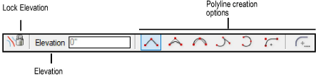
Mode |
Description |
|
Lock Elevation |
Toggles the availability of the Elevation entry mode |
|
Elevation |
When Lock Elevation mode is unlocked, enter an elevation value for the site model contour; otherwise the elevation is obtained by clicking on the site model |
|
Polyline creation options |
Selects the method for drawing the polyline upon which the site model contour is based; see Creating Polylines |

To add a site model contour:
In site model contour editing mode, click the Site Model Contour tool from the Contour Edit palette.
To draw a contour at a specific elevation, toggle Lock Elevation mode to enable data entry and specify the Elevation value.
The contour Elevation can also be specified from the Floating Data bar.
A convenient way of helping you determine the correct elevation for the new contour is to disable Lock Elevation mode and click on the site model where the contour will be created. Press the Tab key to view the Elevation of that point displayed in the Floating Data bar, and click to start drawing the contour line. Then, enable Lock Elevation mode and enter the desired Elevation of the contour.
Draw the polyline to represent the contour. In most cases, the contour should not cross another contour, and no segment of a contour should be collinear with another contour’s segment (occupying the same space in the XY plane).
Double-click to finish drawing the contour.
After exiting the contour editing mode, the contour polyline is automatically converted to a polygon, segmented according to the Segmentation Length value specified in the Site Model Settings. If necessary, new contours are inserted and interpolated. The existing and proposed site models are updated.
~~~~~~~~~~~~~~~~~~~~~~~~~