Creating data tag
stylesCreating data tag
styles
Creating data tag
stylesCreating data tag
stylesThe Vectorworks resource libraries provide many commonly used tags, such as window and door type IDs and date stamps. If you need a tag for a different type of object (such as columns), or to show different data (such as window dimensions), create a custom data tag style.
Creating a tag style allows you to set fixed values for some of the parameters for all instances that use the style, while maintaining the ability to edit other parameters for each instance of the tag. See Concept: Plug-in object styles. Once a tag style is created, you can select it from the Resource Selector on the Tool bar or on the Data Tag Settings dialog box.
To create a data tag style:
1. Do one of the following:
● From the Resource Manager, select an existing data tag resource in the active file to use as a starting point. Right-click on the resource and select Edit from the context menu.
● Select an existing data tag in the drawing to use as a starting point. From the Object Info palette, select Convert to Unstyled from the Style list. Select the Create Plug-in Style command, or right-click on the tag and select New Plug-in Style from Unstyled Plug-in from the context menu. From the Create Symbol dialog box, select the destination folder for the data tag style.
The Data Tag Style dialog box opens.
2. Enter a Style Name.
3. Click the Leader tab to specify options for a tag leader.
![]() Click
to show/hide the parameters.
Click
to show/hide the parameters.
4. Click the Display tab to specify the tag display options.
![]() Click
to show/hide the parameters.
Click
to show/hide the parameters.
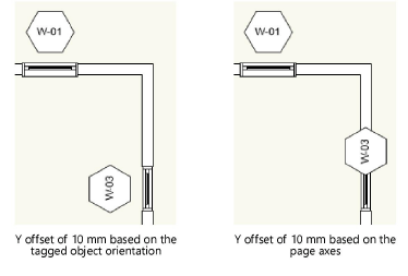
5. Click the Auto-placement tab to specify the options for positioning data tags by default, when they are placed with Select Eligible Objects mode. Measurements are in page units.
![]() Click
to show/hide the parameters.
Click
to show/hide the parameters.
6. Click the Defaults tab, and for each dynamic text object on the tag, specify its next value (for an incrementing field) or the default value (if applicable).
7. From the Display tab, click Edit Tag Layout.
In the tag editing window, draw the geometry of the tag in page units using any planar graphic tools. The origin (0,0) point is always the primary attachment point for a leader line, if used. To define an alternate attachment point, add a 2D locus to the geometry, and enable Allow Multiple Attachment Points in the Data Tag Style dialog box.
8. Use the Text tool to add static and/or dynamic text objects to the tag. From the Object Info palette, specify the appearance of the text; see Formatting text for more information about the options available.
● Static text simply shows the text object on each tag.
● Dynamic text shows data from the tagged object (for example, the width of the window) on each tag, in place of the text object. To create dynamic text, select the text object and click Use Dynamic Text from the Object Info palette. Then click Define Tag Field to open the Define Tag Field dialog box.
![]() Click
to show/hide the parameters.
Click
to show/hide the parameters.
9. When you’re done editing the geometry and text fields on the tag, click Exit Tag Layout Edit and click OK in the Data Tag Style dialog box. The new style is added to the Resource Manager for the current file and is now available for use with the Data Tag tool.
If there is an error in the field definition, such as parameters from two different object types or properties from different IFC entities, an alert displays.
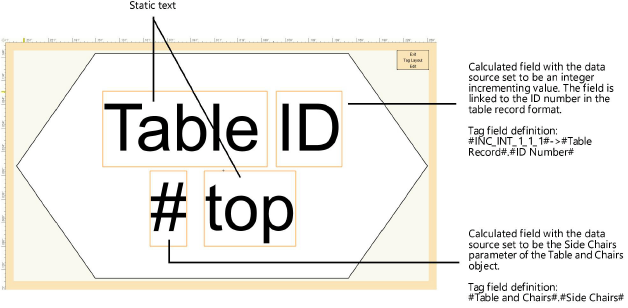
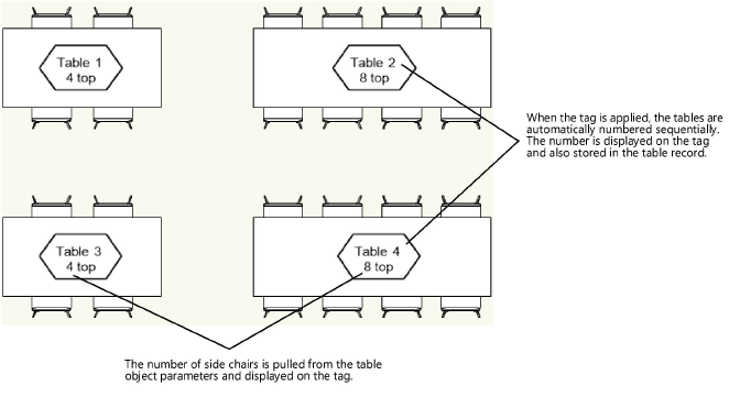
The following example shows a custom tag for table objects. The tag has two static text objects. The two dynamic text fields are a table ID that is automatically incremented with each tag and saved to a record attached to each table, and the number of chairs, which is extracted from the table object itself.
See Creating data tag styles for details.
~~~~~~~~~~~~~~~~~~~~~~~~~