Inserting
a stage rampInserting
a stage ramp
Inserting
a stage rampInserting
a stage rampMode |
Tool |
Tool set |
Modes for The Symbol Insertion tool |
Stage Ramp
|
Event Design |
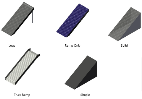
The Stage Ramp tool inserts the type of portable ramp typically used with temporary stage structures. The type, shape, size, appearance, and presence of railings can be customized.
To draw a simple curved ramp, see Workflow: Creating curved ramps.
To insert a stage ramp:
1. Click the tool and the desired insertion modes.
2. Click to place the object in the drawing, and click again to set the rotation.
The first time you use the tool in a file, a properties dialog box opens. Set the default properties. The properties can be edited from the Object Info palette.
![]()
![]() Click
to show/hide the parameters.
Click
to show/hide the parameters.
Parameter |
Description |
Structure |
Select the style of stage ramp
|
Top Height |
Sets the height of the top of the ramp |
Bottom Height |
Sets the height of the bottom of the ramp. If necessary, the ramp’s support structures automatically extend to the defined Z value. |
Width |
Specifies the width of the ramp, not including any railing |
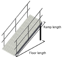
Create Based On |
Specifies the method used to determine the ramp parameters, by setting ramp length, floor length, or pitch. Depending on the selection, certain ramp parameters become available, while the other parameters are calculated for display. ● Ramp Length: Calculates the floor length and the pitch automatically based on the specified ramp length ● Floor Length: Calculates the ramp length and the pitch automatically based on the specified floor length ● Pitch Angle: Calculates the ramp length and the floor length automatically based on the specified pitch angle ● Pitch Ratio: Calculates the ramp length and the floor length automatically based on the specified pitch ratio ● Pitch Percent: Calculates the ramp length and the floor length automatically based on the specified pitch percentage |
Ramp Length |
Sets or displays the length of the ramp |
Floor Length |
Sets or displays the length from the bottom of the ramp to the top of the ramp, as projected to the floor |
Draw Arrow |
Select whether to display an arrow in Top/Plan view; the arrow can point up or down. In the Text Options, select the arrow text label to display the word “Up” or “Down” in the drawing. |
Arrow Size |
When drawing an arrow, sets the arrow head size in drawing units |
Pitch |
|
Angle |
Sets or displays the pitch of the ramp as an angle |
Ratio (rise:run) |
Sets or displays the pitch of the ramp as a rise-over-run ratio |
Percent (Grade) |
Sets or displays the pitch of the ramp as a grade percentage |
Ramp Deck Details |
|
Top Thickness |
Specifies the thickness of the ramp |
Top Color/Texture |
Displays the texture or color selected in the 3D Options |
Trim Height |
Sets the thickness of the ramp trim |
Trim Color/Texture |
Displays the texture or color selected in the 3D Options |
Leg/Structure Details (ramp with legs only) |
|
Diameter |
Sets the diameter of the ramp legs |
Profile |
Select a round, square, or octagonal shape for the legs |
Color/Texture |
Displays the texture or color selected in the 3D Options |
Reference Spacing |
Sets an approximate spacing value for the legs; the exact spacing is determined automatically by evenly dividing the length of the ramp |
Leg Total |
Displays the number of legs |
Railing Details |
|
Show Left/Show Right |
Select whether to show a railing on the left only, right only, or both sides. Railing parameters apply to both sides. |
Height |
Specifies the height of the top railing |
Add’l Railings |
Adds one or more additional railing sets to the ramp, spaced evenly based on ramp width; this parameter is only available when both the left and right railing are selected for display |
Add’l Horiz Bars |
Adds additional horizontal bars to the railing |
Add’l Uprights |
Adds additional upright bars to the railing |
Profile |
Select a round, square, or octagonal railing shape |
Color/Texture |
Displays the texture or color selected in the 3D Options |
Specifies the appearance of applicable ramp elements in 3D views. The 3D Options dialog box opens. For each available portion of the ramp, either select the color from the Color list, or select Custom Texture and then click the current custom texture to open the Resource Selector; double-click a resource to select it. The Object Info palette displays the color or texture selections in the relevant section. The appearance of Simple stage ramps is set from the Attributes palette. |
|
Set Cart ID |
Enter information about the ramp which can be placed in the drawing with Text Options (does not affect the stage appearance) |
Note |
Adds a note, which can be placed in the drawing with the Text Options |
Text Options |
Opens the Text Options dialog box, to enable the display and format the text of labels |
Default Text Positions |
Restores text labels to their default positions |
Opens the Classes dialog box, to specify class naming for the various portions of the stage ramp. This allows portions of the stage ramp to be set to visible, grayed, or invisible. Use the suggested standard class, select a class from the list of classes present in the drawing, or create a new class. Select <Stage Ramp Class> to place the stage ramp element in the same class as the stage ramp. ● Class Prefix: Specifies an optional default root class naming standard for all stage ramp parts; click Use Standard Classes to begin all stage ramp class names with the prefix, so that they are sorted together. ● Use Standard Classes: Sets the class names for all stage ramp elements to the default suggested standard names, using the Class Prefix if there is one. ● Stage ramp elements: For each portion of the stage ramp, including the loci that represent the center of the stage ramp legs for certain Structure types, specifies the class name standard; the class names shown here are applied to the elements. |
|
Update |
Updates the object when changes have been made to the Object Info palette parameters |
~~~~~~~~~~~~~~~~~~~~~~~~~
Workflow: Creating curved ramps