 Creating a graticuleCreating a graticule
Mode |
Tool |
Tool set |
Rectangle
Modes for the Polyline tool |
Graticule
|
GIS |
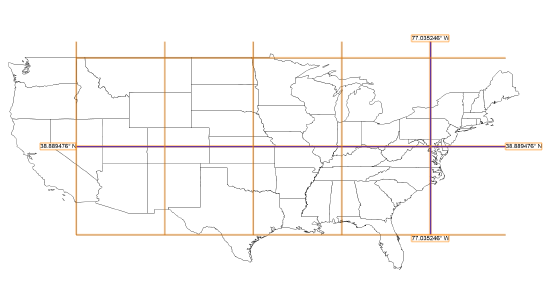
Use the Graticule tool to place a reference grid of real world parallels, meridians, and labels, showing the Earth’s orientation in a given area of the drawing. Unlike a grid that is based on X and Y coordinates, the graticule lines are based on longitude and latitude lines that are inferred from the georeferenced coordinate system.
The Document Georeferencing dialog box opens if the document is not yet georeferenced, to select a coordinate system. See Specifying document georeferencing.
To create a graticule:
1. Click the tool and one of the insertion modes. Draw Rectangular Area places the graticule grid in a rectangular area, while Draw Polylinear Area draws a polyline for the graticule area.
2. Click Preferences.
The Graticule Preferences dialog box opens.
![]() Click
to show/hide the parameters.
Click
to show/hide the parameters.
3. Click and drag in the drawing to create the rectangular or polyline boundary in the approximate location of the latitude and longitude lines you specified. Make the area larger than the graticule will be, so the graticule will not be cut by the rectangle or polyline. When you complete the shape, a graticule object is created over the specified location.
The graticule parameters can be edited from the Object Info palette.
~~~~~~~~~~~~~~~~~~~~~~~~~

