 Step 2: Create and copy a wrapper nodeStep 2: Create and copy a wrapper node
Wrap the network of nodes to make the script more readable on the monitor, and to make it easy to duplicate the code.
To create a wrapper node:
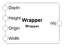
1. Right-click on any node in the network, and select Wrap Marionette Network from the context menu.

The network becomes a wrapper node.
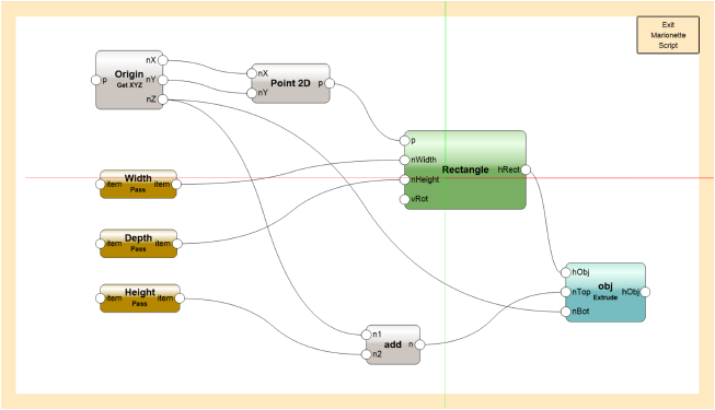
To allow inputs and outputs to the wrapper, the wrapped nodes must be named. In this example, you need to provide access to the origin of the rectangular prism, its dimensions (width, depth, and height), and the resulting extruded object.
2. Double-click on the wrapper to enter object editing mode and access the Marionette script inside the wrapper.
3. Select each node listed, and enter its Name in the Object Info palette.
|
Node |
Name |
|
Get XYZ |
Origin |
|
Pass (attached to Width input on Rectangle node) |
Width |
|
Pass (attached to Height input on Rectangle node) |
Depth |
|
Pass (attached to Add node) |
Height |
|
Extrude |
obj |
4. Click Exit Marionette Script to return to your drawing. The wrapped network displays with the named nodes that can be accessed.
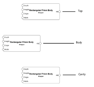
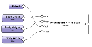
5. Select the wrapper node, and enter the Name Rectangular Prism Body in the Object Info palette.
6. Make two copies of the Rectangular Prism Body wrapper. These will serve as the basis for the cabinet top and cavity in future steps; the parameters will be redefined for each piece of the cabinet.
7. On the original wrapper node (the body), attach a 3D Point node to the Origin port and a Dimension node to each of the other ports. Connect the wires.
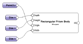
8. Select each Dimension node, and assign the following names and dimension values in the Object Info palette.
|
Body prism port |
Dim node name |
Value |
|
Width |
Body Width |
3 feet |
|
Depth |
Body Depth |
2 feet |
|
Height |
Body Height |
3.5 feet |
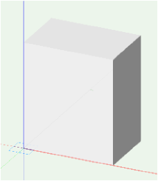
9. Select a node and click Run from the Object Info palette.
The rectangular prism displays with its bottom front left corner at the assigned origin (0,0,0). This is the cabinet body. The prisms that compose the cabinet top and cavity are defined relative to the origin and dimensions of this base object.
You can download the tutorial at this stage here (internet access required).
~~~~~~~~~~~~~~~~~~~~~~~~~