 Detail callouts and detail-callout markersDetail callouts and detail-callout markers
Detail callouts and detail-callout markers look very similar on the drawing, but they’re created differently.
A detail callout is automatically created when a detail viewport is created. The detail callout and the detail viewport are linked, as described in Creating detail viewports. Specify the graphic properties of the detail callout (such as marker style) when you create the detail viewport. To modify the detail callout, or to change the view in the detail viewport that is linked to the detail callout, see Editing detail callouts. To access a detail callout from its detail viewport, click Detail Callout Instances from the Object Info palette (see Detail callout instances).
A detail callout that has been pasted from a copy, duplicated, or mirrored from a detail callout that is associated with a detail viewport becomes an “unlinked” detail callout. It displays with black and yellow stripes. In the Object Info palette, Detail Viewport displays Not Linked.
A detail-callout marker is graphically similar to a detail callout, but it’s not necessarily linked to a viewport. Use the Detail-Callout Marker tool from the Dims/Notes tool set to insert a marker. Click Preferences to specify the graphic properties of the object before you create it.
A detail-callout marker can be linked to a viewport. Depending on the type of viewport it is linked to, its drawing number and sheet number are synced to the selected viewport, similar to a detail callout. Detail-callout markers that are linked to a viewport display with a green link icon next to the marker symbol. The linked detail-callout marker can have different graphic properties from a detail callout that is also associated with a detail viewport.
Tool |
Tool set |
Detail-Callout Marker
|
Dims/Notes |
To create a detail-callout marker, either use the Detail-Callout Marker tool or create a polyline and then select the Create Objects from Shapes command (see Creating objects from shapes).
The following modes are available.
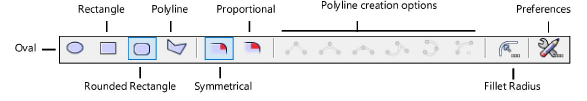
Mode |
Description |
Oval |
Creates an oval detail-callout marker using Box mode; see Creating ovals |
Rectangle |
Creates a rectangular detail-callout marker using Corner to Corner mode; see Creating rectangles |
Rounded Rectangle |
Creates a rounded rectangular detail-callout marker using Proportional or Symmetrical mode; see Creating rounded rectangles |
Proportional |
Click to draw a rounded rectangular detail-callout marker with proportional corners |
Symmetrical |
Click to draw a rounded rectangular detail-callout marker with symmetrical corners |
Fillet Radius |
Enter the corner radius for a symmetrical rounded rectangular detail-callout marker |
Polyline |
Creates a polyline detail-callout marker using the six polyline creation options |
Polyline creation options |
Select one of six types of control points for the vertices of the polyline; see Creating polylines. The Fillet Radius value for Arc Vertex Polyline mode is independent of the Fillet Radius value for Symmetrical Rounded Rectangle mode. |
Preferences |
Sets the default parameters for detail-callout markers |
To insert a detail-callout marker:
1. Click the tool and then click Preferences to set the default parameters for detail-callout markers.
2. Click a drawing mode from the Tool bar, and do one of the following:
● For a detail-callout marker in the shape of an oval, rectangle, or rounded rectangle, click to begin the shape, and then click to complete the shape and create the detail-callout marker.
● For a polyline detail-callout marker, click to begin the polyline, and then click to set each polyline vertex. Click the start point (for a closed polyline) or simply double-click to complete the polyline and create the detail-callout marker.
After creation, edit detail-callout markers as follows:
● Use the Object Info palette to edit the graphic properties (such as the marker style).
● Use the Attributes palette to apply attributes (such as the fill or pen color).
● Use options on the Text menu to control the text appearance (such as the font or size), or assign a text style.
● Use the Selection tool to adjust the marker label, or to move the entire detail-callout marker.
● Use the Reshape tool to reshape the detail-callout marker.
There are two reshape modes for both oval and rounded rectangular detail-callout markers. To reshape an oval detail-callout marker, click Polyline or Oval mode from the Tool bar. To reshape a rounded rectangular detail-callout marker, click Polyline or Rounded Rectangle mode. (See 2D reshape modes.)
● To link a detail-callout marker to a viewport, select the viewport from the Link To Viewport list on the Object Info palette.
Parameters display on the Object Info palette for selected detail callouts and detail-callout markers. Many of these parameters also display on the Detail Callout Settings dialog box, which you can access to edit when you create a detail viewport. If there are multiple instances of a detail callout, all instances are updated.
![]() Click
to show/hide the parameters.
Click
to show/hide the parameters.
~~~~~~~~~~~~~~~~~~~~~~~~~

