Placing redlines Placing redlines
 Tool |
Tool set |
Redline
|
Dims/Notes |
Use the Redline tool to create redline objects, which are graphical time-stamped change requests on the drawing.
Several modes are available.
To redline an object or area:
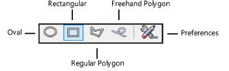
1. Click the tool and mode.
2.Click Preferences to open the Place Redline dialog box and specify the tool’s default parameters. The parameters can be edited later from the Object Info palette.
![]() Click
to show/hide the parameters.
Click
to show/hide the parameters.
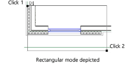
3.On the design layer where the revision is to be performed, draw the redline around the revision area.
Based on the selected creation method, the appropriate tool creates the redline. This allows the use of SmartCursor cues, object snapping, and boomerang mode when drawing redlines.
4.The Place Redline dialog box opens. Enter the redline information and authorization.
![]() Click
to show/hide the parameters.
Click
to show/hide the parameters.
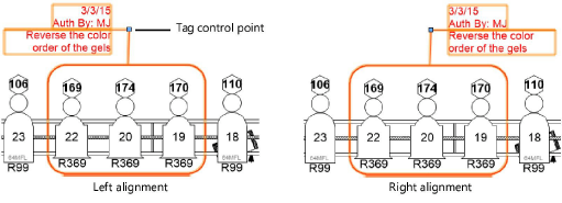
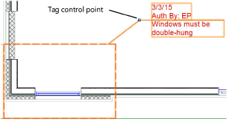
5.The redline object indicates the current date and the drawing condition to be corrected. Position redline text by clicking on the tag control point and dragging the tag to the desired location. If there are several redline objects, use the Align/Distribute Leader Lines command to improve readability (see Aligning and distributing leader lines).
The parameters of one or more selected redline objects can be edited later from the Object Info palette.
![]() Click
to show/hide the parameters.
Click
to show/hide the parameters.
~~~~~~~~~~~~~~~~~~~~~~~~~