Inserting
fastener objects using the Fastener toolInserting
fastener objects using the Fastener tool
Inserting
fastener objects using the Fastener toolInserting
fastener objects using the Fastener toolTool |
Tool set |
Fastener
|
Fasteners |
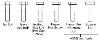
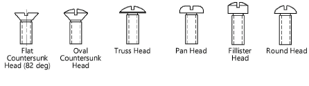
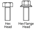
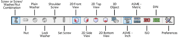
Several types of fastener objects can be inserted by clicking the Fastener tool and specifying object parameters from the Tool bar.
Mode |
Description |
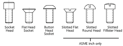
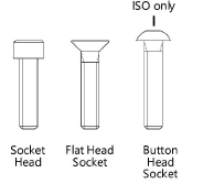
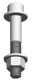
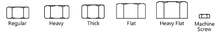
Screw or Screw/Washer/Nut Combination |
Inserts a screw and nut object which can be composed of a variety of screw, washer, and/or nut components; hex bolts, square bolts, hex screws, cap screws, and machine screws can all be inserted using this tool mode |
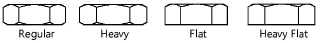
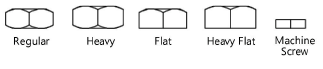
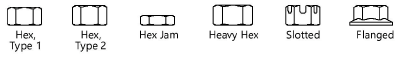
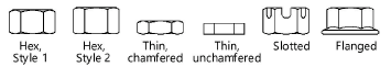
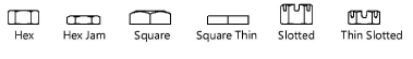
Nut |
Inserts a nut object, including hex, hex jam, slotted hex, and square nuts |
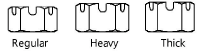
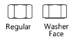
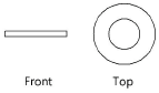
Plain Washer |
Inserts a plain washer object |
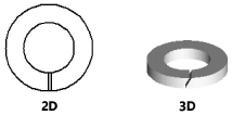
Lock Washer |
Inserts a lock washer object |
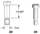
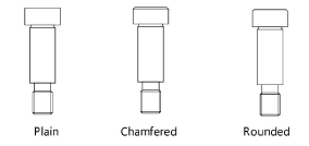
Shoulder Screw |
Inserts a shoulder screw object |
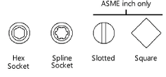
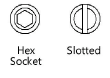
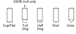
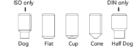
Set Screw |
Inserts a set screw object |
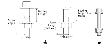
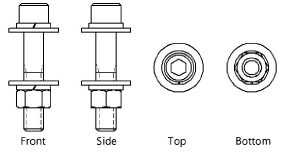
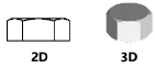
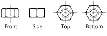
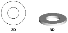
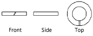
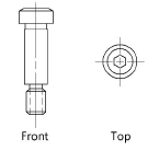
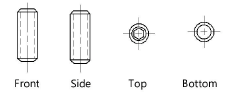
2D Front View |
Inserts the selected item as a 2D object in front view |
2D Side View |
Inserts the selected item as a 2D object in side view |
2D Top View |
Inserts the selected item as a 2D object in top view |
2D Bottom View |
Inserts the selected item as a 2D object in bottom view |
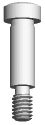
3D Object |
Inserts the selected item as a 3D object |
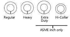
ASME Inch |
Inserts the selected object using ASME inch standards |
ASME Metric |
Inserts the selected object using ASME metric standards |
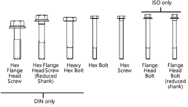
ISO |
Inserts the selected object using ISO standards |
DIN |
Inserts the selected object using DIN standards |
Preferences |
Opens the Preferences dialog box for specification of additional object parameters |
To insert a fastener object:
1. Click the tool and click the desired fastener object.
2.Click the Tool bar button to insert either a 2D object in a specific view or a 3D object.
For objects that do not have bottom view (because it is the same as the top view), the top view is drawn when either the 2D Top View or 2D Bottom View mode is clicked. The same applies to the front and side view.
3.Click the Tool bar button to insert the object using ASME (inch or metric), ISO, or DIN standards.
4.Click Preferences to specify additional object parameters before placing the object in the drawing. Parameters vary based on the object selected for insertion, and show the available variations for a specified object size. Additional parameters display in the Object Info palette. Refer to the following table for detailed object parameter information.
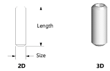
5.If inserting a linear object (such as a bolt, screw, or screw and nut object), click in the drawing area to set the start point, drag to set the object’s length, and click again to set the object’s end point. For all other objects (such as washers and nuts), click in the drawing area to place the selected point object.
Parameters can be edited later from the Object Info palette.
![]() Click
to show/hide the parameters.
Click
to show/hide the parameters.
![]() Click
to show/hide the parameters.
Click
to show/hide the parameters.
![]() Click
to show/hide the parameters.
Click
to show/hide the parameters.
![]() Click
to show/hide the parameters.
Click
to show/hide the parameters.
~~~~~~~~~~~~~~~~~~~~~~~~~