 Workflow: Creating multi-cell symbol definitionsWorkflow: Creating multi-cell symbol definitions
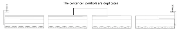
Multi-cell symbols consist of individual lighting device symbols combined to create a multi-cell container symbol. For example, a four-cell cyc symbol is created from four nested cell symbols: one left, two center, and one right. Depending on how the multi-cell device will hang, some cell symbols can be identical (duplicated). For example, a four-cell cyc unit that hangs horizontally on two end clamps can use identical symbols for the center cells and unique symbols for the left and right cells where the clamps are attached.
The following workflow describes how to create the nested cell symbols and combine them to form the multi-cell container symbol definition. The process of creating each cell symbol is similar to creating a standalone lighting device (see Workflow: Creating lighting device symbol definitions), but there are some important distinctions.
Once the multi-cell symbol definition is created, use the Lighting Device tool to place a lighting device symbol instance on the light plot.
To create each cell symbol of a multi-cell unit:
1. Draw the 3D geometry for the cell symbol. Follow the steps described in Creating the 3D geometry, but keep in mind these special considerations for cell symbols:
● Depending on the cell’s position within the multi-cell unit, it might not need a yoke or base component.
● Each cell symbol has multiple lenses. Use the Align and Distribute tool to duplicate and distribute the lenses within the cell.
● Multi-cell symbols can have multiple light emitters. You must add the emitters when creating the cell symbol, but you can wait to define each emitter’s controller cell until you create the multi-cell container symbol; see Light emitters in multi-cell devices for an explanation of the options.
2.Create the 3D symbol, as described in Creating the 3D symbol definition.
3.Attach the Parts record to the 3D components. Follow the steps described in Attaching the Parts record to the lighting device, but keep in mind the following special considerations for cell symbols:
● You can group all the lenses and attach the Parts record to the group instead of attaching the record to each lens individually. Then you can group the grouped lenses with the body geometry to form the body part.
● If you placed 3D loci for emitters, you can use the Parts record to assign each emitter to a controller cell. You should do this now only if the cell symbol will not be used in other multi-cell symbols where its emitters will require different cell # assignments. Follow the steps in Defining the accessory’s default position.
4.Draw the 2D geometry for the cell symbol, as described in Creating the 2D geometry. The end of the cell that emits light should point to the top of the drawing in Top/Plan view.
If one cell hangs under another cell so that it is obscured in 2D views, the under-hung cell does not require a 2D representation. It should be 3D-only; otherwise, the symbol may display incorrectly when rotated.
5.Align the 2D and 3D versions of the symbol so the insertion points line up.
The 2D insertion point is the hanging point.
6.Select all 2D and 3D components, and select Modify > Create Symbol.
The Create Symbol dialog box opens; see Creating symbol definitions for an explanation of the parameters.
7.Attach the Light Info Record as described in Attaching the Light Info Record and Light Info Record M, but only fill in the cell-specific data. For example, the Position and Weight need not be defined.
The cell-specific data is transferred to the appropriate cell in the multi-cell unit. The data does not apply to the parameters shared by all cells; these global parameters are specified by the Light Info and additional records attached to the multi-cell container symbol.
See Spotlight preferences: Lighting Devices: Parameters pane for information about attaching additional records with default data for lighting devices.
To be properly inserted with the Lighting Device tool, the multi-cell symbol must only contain other symbols, not lighting device objects.
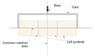
Multi-cell lighting devices focus in 3D in the same way as individual lighting devices. The yoke is created from portions of the nested cell symbols. The 3D locus point, placed within the multi-cell container symbol, is used as a common rotation axis for the entire multi-cell unit.
1. Use the Symbol Insertion tool to place the individual cell symbols on the design layer, aligned as desired for the multi-cell lighting device.
Alternatively, locate the cell symbols in the Resource Manager and drag them into the drawing. Do not double-click the cell symbols in the Resource Manager or use the Lighting Device tool to insert them.
2.Place a 3D locus within the multi-cell unit at the rotation point for the yoke.
3.Select all the cell symbols and select the Create Symbol command to create the multi-cell container symbol.
4.Attach the Parts record to the 3D locus (rotation point), as described in Attaching the Parts record to the lighting device.
5.If you did not previously define which cells control the light emitters, attach the Parts record to each emitter’s 3D locus point. Assign a Light Emitter value using the method described in Defining the controller cell.
6.Attach the Light Info Record as described in Attaching the Light Info Record and Light Info Record M, but only fill in the global device data.
All information from the Light Info Record and additional records attached to the multi-cell container symbol is transferred to the parameters of the multi-cell lighting device. If a parameter is defined as Multi-cell in the parameters list on the Spotlight preferences: Lighting Devices: Parameters pane, the data is cell-specific.
Multi-cell symbols can support multiple light emitters when rendering. Placing a 3D locus at the site of each emitter allows you to precisely position the light source and identify which emitters should work together. The Light Emitter value in the Parts record defines which cell controls the emitter’s light properties (this might not be the cell where the emitter is located). All 3D loci with the same Light Emitter value will have the same light properties.
You can define the controller cells for the light emitters either when creating the cell symbols or when creating the multi-cell container symbol. If you plan to use a cell symbol within various container symbols that have different cell counts, save this step for when you create the container symbol.
Adding many light emitters can significantly slow the rendering.
The Parts record defines which cell in the multi-cell symbol controls each emitter’s light properties.
To define the controller cell, do the following for each emitter:
1. Select the symbol (either the cell symbol or the multi-cell container symbol), and select Modify > Edit Symbol.
2.In the Edit Symbol window, select the emitter’s 3D locus.
3.Click the Data tab on the Object Info palette.
4.Click Attach Record to open the Resource Selector, and double click the Parts record to attach it.
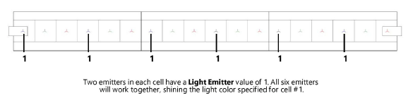
5.Enter a Light Emitter value indicating which cell in the multi-cell unit will control the emitter’s light properties. Enter the same value for emitters that need to shine the same light color. For example, enter 1 for each emitter that should use the color specified for cell #1 (see Concept: Multi-cell lighting devices for more information about cell index numbers).
If the Light Emitter value does not match the index number of a cell in the multi-cell unit, an emitter is not created.
~~~~~~~~~~~~~~~~~~~~~~~~~