 Creating
a spoil pile areaCreating
a spoil pile area
Creating
a spoil pile areaCreating
a spoil pile areaMode |
Tool |
Tool set |
Spoil Pile
|
Site Modifiers
|
Site Planning |
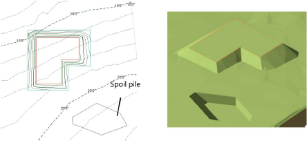
A spoil pile refers to an area where excess earth is used to help balance the cut and fill, so that the site does not require earth to be moved in or out. A spoil pile area applies an even thickness of cut or fill for the site. To create a spoil pile, either use the Site Modifiers tool, or draw a polyline and then select the Create Objects from Shapes command (see Creating objects from shapes).
To create a spoil pile area:
1. Create the site model and add any modifiers, such as pads and roads, and update the proposed site model by clicking Update from the Object Info palette of the selected site model.
2.The initial cut and fill volumes are displayed in the Object Info palette.
3.Click the tool and mode. Specify the pad elevation from the Tool bar if desired.
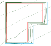
4.Draw the spoil pile area.
5.In the Object Info palette, adjust the elevation of the spoil pile up or down depending on whether fill is required or excess fill is present.
![]() Click
to show/hide the parameters.
Click
to show/hide the parameters.
6.Select the site model and click Update from the Object Info palette.
7.With the site model still selected, click Update Cut and Fill Calculations from the Object Info palette.
Evaluate the results of the spoil pile by checking the Net C&F Volume results in the Object Info palette of the selected site model. If the spoil pile elevation needs adjustment, select the spoil pile and enter a new Elevation value from the Object Info palette. Then select the site model, click Update, and then click Update Cut and Fill Calculations.
8.Continue adjusting the spoil pile elevation until a balanced cut and fill volume is achieved.
Display the 3D cut and fill volumes by selecting Cut and Fill as the 3D Display from the Object Info palette of a selected site model. The cut and fill colors are specified on the Site Model tab of the Graphic Properties dialog box. In addition, a 2D polygonal representation of the cut and fill area can be displayed by selecting 2D Cut & Fill Area from the Site Analysis tab.
~~~~~~~~~~~~~~~~~~~~~~~~~

