 Creating elevation benchmarks
|
Mode |
Tool |
Tool set |
|
Modes for Creating lines |
Elevation Benchmark
|
Dims/Notes |

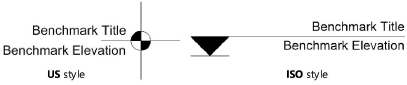
Use the Elevation Benchmark tool to indicate the height of an object in an elevation drawing. Two elevation benchmark styles are available: ISO and US.
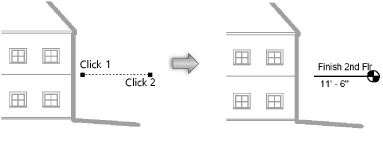
To create an elevation benchmark:
Click the tool and mode.
Click to place the object in the drawing, and click again to set the rotation. The first time you use the tool in a file, a properties dialog box opens. Set the default parameters. The parameters can be edited later from the Object Info palette.
Click to show/hide the parameters.Click to show/hide the parameters.
|
Parameter |
Description |
|
Rotation |
Specifies the number of degrees to rotate the object (0.00 is horizontal) |
|
Text Style |
Select a text style from a library or the current file. To use the style defined for the object’s class, select <Class Text Style>. To format the text using options on the Text menu, select <Un-Styled>. See Using text styles and Formatting text. |
|
Title |
Specifies the benchmark title value |
|
Title Text Max Width |
Enter the maximum width of the title text. The title text wraps and adds as many lines as necessary to fit the complete text within the specified width. A control point on the text box allows the width of existing text to be changed manually. |
|
Elevation Display |
Select the method for calculating the benchmark’s elevation value. Custom: Allows you to manually input a Custom Elevation value Z value relative to ground plane: Uses the Z value of the elevation benchmark marker, plus the elevation of the object’s layer, to determine the elevation value Z value relative to reference elevation: Uses the Z value of the elevation benchmark marker, plus the elevation of the object’s layer, minus the Reference Elevation value, to determine the elevation value Y value relative to reference elevation: Uses the Y value of the elevation benchmark marker, minus the Reference Elevation value, to determine the elevation value Distance from control point: Allows the elevation value to be referenced from a control point displayed on the drawing, rather than from the drawing’s active layer plane. If the control point is moved, the elevation value remains set by the distance from the control point to the elevation benchmark object. This allows you to set a control point at the ground floor of a house, for example, so that the elevation benchmark value is set according to the height from the ground floor. |
|
Custom Elevation |
If Elevation Display is set to Custom, specifies the benchmark elevation value |
|
Reference Elevation |
If Elevation Display is set to Z Value Relative to Reference Elevation or Y Value Relative to Reference Elevation, specifies the reference elevation value |
|
Style |
Select the marker style
|
|
Line Position |
For ISO style, specifies the position of the line relative to the marker |
|
Title Position |
Specifies the position of the title text relative to the line and marker |
|
Elevation Position |
Specifies the position of the elevation value relative to the line and marker |
|
Marker Orientation |
Select the marker orientation (left or right) |
|
Marker Graphics |
Select a marker style from the list; styles include filled, unfilled, and for ISO style half-filled versions. For the half-filled style, the left half is filled and the right half is unfilled. |
|
2D Scale Factor |
Specifies the elevation benchmark size; increase the scale value to obtain a larger object |
|
Crosshair Scale Factor |
For US style, increases the size of the elevation benchmark crosshairs, extending them beyond the marker circle. For ISO style, when the Line Position is Top of Marker, draws a horizontal line at the bottom of the marker; a scale factor of 0 draws no line, and a scale factor of 1 makes the line the same width as the marker.
|
|
Marker Size |
For ISO style, specifies the marker size; increase the size value to obtain a larger marker |
|
Use Offset |
Adds an offset to the elevation benchmark’s leader line (available only from the Object Info palette after the elevation benchmark object is placed).
For ISO style when the Line position is set to Top of Marker, a different type of offset can be created by increasing the 2D Scale Factor and decreasing the Marker Size. |
|
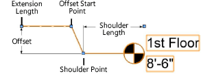
Offset |
Specify the size of the offset. A control point on the offset start point allows the offset to be moved horizontally to change the angle of the offset line. It cannot be moved horizontally past the shoulder point. |
|
Shoulder Length |
Specify the shoulder length. A control point on the shoulder point allows the shoulder length to be changed manually. The control point can be moved horizontally to adjust the shoulder length; the offset start point moves with it to maintain the angle of the offset line. The control point can also be moved vertically to adjust the offset; the marker moves with it. |
|
Extension Length |
Specifies the length of the object line leading to the offset start point (available only from the Object Info palette after the elevation benchmark object is placed). Only the extension length is drawn with the benchmark object’s line style set in the Attributes palette. The line portions extending from the offset start point to the marker remain solid. |
|
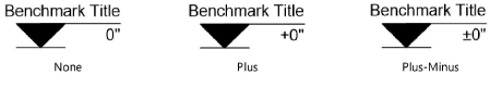
Prefix |
Select a prefix for the elevation benchmark. The prefix (if selected) and elevation value placement are controlled by the Title Position and Elevation Position. |

After creation, multiple elevation benchmark objects can be aligned and distributed with the Align/Distribute Leader Lines command; see Aligning and distributing leader lines.