 Placing a video camera
|
Tool |
Tool set |
|
Video Camera
|
Event Design Visualization |

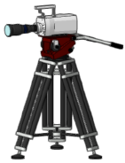
For use by event designers, the Vectorworks Spotlight video camera object includes a variety of lenses, camera bodies, and stand types, to mimic real-world video camera options. The video camera’s active view displays a view similar to a real video camera using the same lens, camera body, and stand type as in the actual event space. The active view updates live as settings change, so designers can plan the lighting and shots needed for the production.

To insert a video camera:
Click the tool.
Do one of the following:
Click Lens, Body, and/or Stand on the Tool bar to select resources from the Resource Selector.
Click Preferences to open the Object Properties dialog box and specify the tool’s default parameters.
Some parameters can be edited later from the Object Info palette; other parameters are defined by the symbols selected for the Lens, Body, and Stand, and their records. Parameters defined by the symbol can be changed only by creating a new symbol definition, with associated geometry and 3D loci for insertion points, and/or a new record. See Creating symbol definitions or Editing symbol definitions and Editing default record values for a symbol definition.
The Units settings: Dimensions pane sets the decimal precision for the Fine Tune Camera and Lens parameters.
Click to show/hide the parameters.Click to show/hide the parameters.
|
Parameter |
Description |
|
Position |
Enter a position note that can be displayed in the drawing and/or in a report |
|
Name |
Enter a unique name that can be displayed in the drawing and/or in a report |
|
Activate Camera (Object Info palette only; displays when no camera is activated) |
Changes the document view to the camera view and displays the image that the real-world camera will capture within the viewfinder indicator. Enables the Renderworks camera effects when rendering in Final Quality Renderworks or Custom Renderworks render modes. The camera can also be activated by double-clicking it with the Selection tool and from the Visualization palette; see Managing lights and cameras with the Visualization palette. Use the multiple view panes feature (see Using multiple drawing views) to view the camera in a third-person view and in first-person camera view simultaneously. When the views are linked, the camera view updates in real time when the video camera object is edited. |
|
Deactivate Camera (Object Info palette only; displays when a camera is activated) |
Unlinks the camera from the current view so that viewing tools do not affect the camera view, disables the Renderworks camera effects when rendering in Final Quality Renderworks or Custom Renderworks render modes, and returns you to the previous view. The camera can also be deactivated by changing the view so the camera is no longer active. |
|
Render Mode |
Select a render mode for the 3D camera view; see Rendering modes |
|
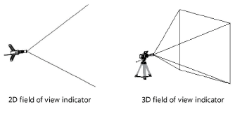
Show Field of View |
Select how to display the field of view indicator, which provides an idea of what the camera will capture, from an inactive camera view
|
|
Auto update 3D view |
Automatically updates the 3D camera view with every parameter change. For complex models with many adjustments, this can slow down processing. Temporarily deselect this option until the changes are made, and then either select it or click Activate Camera on the Object Info palette to update the camera view. |
|
Format |
If the video camera’s record contains the camera format, it displays. If the record doesn’t contain the format, select the desired format. Select Camera Default or Custom Aspect to enter a Custom Format. |
|
Fine Tune Camera |
|
|
Aim Camera (Object Info palette only) |
Click to aim the selected camera at a selected point on the drawing; the cursor changes to indicate the operation is active. Click on the drawing to aim the camera. |
|
Focus Point |
Specify a focus point object for the camera; see Focusing lighting devices |
|
Pan Left/Right |
Pans the camera left/right about its axis within a 180° range, as though it were on a tripod; enter the value or drag the slider |
|
Tilt Up/Down |
Tilts the camera vertically about its axis within a +/- 90° range, as though it were on a tripod; enter the value or drag the slider |
|
Rotate Camera L/R |
Rolls the camera about its axis within a +/- 20° range, as though it were on a tripod; enter the value or drag the slider |
|
Lens |
|
|
Resource Selector |
Displays the currently selected resource; to change it, locate the desired resource and double-click to activate it |
|
Focal Length |
Set the lens’s focal length; the Diagonal Angle of View automatically updates |
|
Diagonal Angle of View |
Set the diagonal angle of the view; the Focal Length automatically updates |
|
Minimum Focus Distance |
Displays the minimum distance in mm between the camera and the point of focus, using the selected lens |
|
Aperture |
Displays the aperture range supported by the selected lens |
|
Camera Body |
|
|
Resource Selector |
Displays the currently selected resource; to change it, locate the desired resource, and double-click to activate it |
|
CCD/Sensor Format |
Displays the CCD/sensor size of the selected camera body |
|
For DPI of |
Displays the calculated pixel size when exporting the camera view. This has no effect on the camera view. |
|
Maximum Resolution |
Displays the maximum resolution in megapixels supported by the selected camera |
|
Crop Frame Scale % |
Scales both the size of the clipping window frame when in a cropped perspective projection, and the perspective distance; both the crop frame and the drawing appear scaled |
|
Stand Type |
|
|
Use symbol for stand |
Includes stand type details |
|
Resource Selector |
Displays the currently selected resource; to change it, locate the desired resource, and double-click to activate it |
|
Wheels |
Displays the number of wheels on the selected stand, if any |
|
Gimbal Points |
Displays the number of gimbal points on the selected stand |
|
Articulation Points |
Displays the number of articulation points on the selected stand |
|
Height |
Displays the height of the selected stand |
|
Camera Effects |
See Placing a Renderworks camera for descriptions of the available effects |
|
Depth of field |
Uses the depth of field options |
|
F-Stop |
Select a value, or select Custom F-Stop |
|
Custom (f/#) |
If F-Stop is set to Custom F-Stop, enter a custom value equal to or greater than 0.01 |
|
Focus Distance |
Specify the focus distance numerically or click Click to Set Focus Distance to define the focus distance based on objects in the drawing |
|
Iris Shape |
Select the iris shape |
|
Exposure |
Uses the exposure options |
|
ISO Film Speed |
Select an ISO film speed |
|
Shutter Speed |
Select the shutter speed, or select Custom Speed |
|
Custom Speed (s) |
If Shutter Speed is set to Custom Speed, enter a custom value |
|
Bloom (%) |
Enter a bloom percentage; values greater than 100% are accepted |
|
Vignetting Intensity (%) |
Enter a vignetting intensity percentage; values greater than 100% are accepted |
|
Vignetting Offset (%) |
Enter a vignetting offset percentage |
|
Chromatic Aberration (%) |
Enter a chromatic aberration percentage; values greater than 100% are accepted |
|
To control appearance and visibility for the camera parts and fields of view, click to open the Classes dialog box. For each part, select a class from the list of classes present in the drawing, or create a new class. |
Click to place the object, and click again to set the rotation.
