Worms
Worms
|
Mode |
Tool |
Tool set |
|
Modes for The Symbol Insertion tool |
|
Machine Components |

Multiple worm and worm gear tools share the same position on the tool set. Click and hold the mouse on the visible tool to open the Pop-out tools list and select the desired tool.
To insert a worm:
Click the tool and mode.
Click to place the object, and click again to set the rotation. The first time you use the tool in a file, a properties dialog box opens. Set the default parameters. The parameters can be edited later from the Object Info palette.
Click to show/hide the parameters.Click to show/hide the parameters.
|
Parameter |
Description |
|
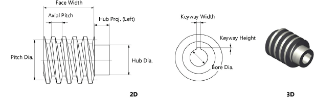
Pitch Diameter |
Enter the pitch diameter |
|
Axial Pitch |
Enter the axial pitch |
|
Pressure Angle (deg.) |
Select the pressure angle in degrees |
|
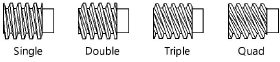
Number of Starts |
Select the number of starts
|
|
Tooth Profile |
Select the type of tooth profile
|
|
Face Width |
Enter the width of the worm face |
|
Draw Hub(s) |
Draws a hub |
|
Hub Diameter |
Enter the hub diameter |
|
Hub Projection (Left/Right) |
Specify the amount of projection for the hub on both the left and the right; a negative value indicates that the hub face is recessed |
|
Draw Bore |
Draws a bore |
|
Bore Diameter |
Enter the bore diameter |
|
Keyway |
If a keyway is present, select the square, rectangular, or custom size. The square and rectangular selections apply the ASME-recommended size based on the bore diameter. |
|
Keyway Width/Height |
For custom keyway sizes, enter the width and height values of the keyway |
|
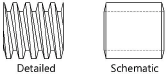
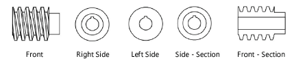
View (2D only) |
Select the 2D view
|
|
Show Center Lines (2D only) |
Draws the worm with center lines |