Setting document preferences
Document preferences apply only to the current drawing, and they remain in effect until they are changed. When you create a template, the current document preferences are saved with the template (see Concept: Templates).
To change the preference settings in the document:
Select the command.
The Document Preferences dialog box opens.
Click each tab to set the document preferences for that tab.
Document preferences: Display tab
Click the Display tab to set the display preferences.
Click to show/hide the parameters.Click to show/hide the parameters.
|
Parameter |
Description |
|
Black and white only |
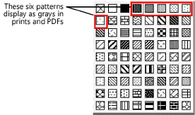
Draws objects using only the colors black and white (black items display as black, and all colors—including gray—display as white); this choice overrides any other color settings (including viewport settings) and is used mainly for printing on black and white printers. A selected viewport data visualization (Design Suite required) overrides this option. To create a “grayscale” effect for prints and PDFs when this feature is enabled, use pattern fills instead of solid color fills. Set the pattern foreground color to black, and set the background color to any other color. Patterns 4 through 9 in the pattern fill selection box display as various shades of gray.
|
|
Auto-display detail levels for design layers |
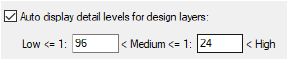
For symbol definitions with detail levels defined for 3D components (see Customizing detail levels for 2D and 3D components of symbol definitions and plug-in objects), automatically displays the detail levels specified for the design layer scale. Define the scales at or below which the design layer displays the Low and Medium detail levels; the High detail level automatically displays for drawings with a scale above the level defined for Medium. For example, for imperial scales, entering the numbers 96 and 24 into the fields, as shown, results in the following behavior.
Low detail if scale is 1:96 (1/8"=1'-0") or smaller Medium detail if scale is 1:24 (1/2"=1'-0") or smaller, but larger than 1:96 High detail if scale is larger than 1:24 For metric scales, entering the numbers 100 and 25 results in the following behavior. Low detail if scale is 1:100 or smaller Medium detail if scale is 1:25 or smaller, but larger than 1:100 High detail if scale is larger than 1:25 Wall, slab, and roof components display at settings Medium and High. |
|
Save viewport cache |
Saves a viewport cache in the file; saving the cache may increase file size, but saves time when files that contain viewports are opened. If deselected, any viewports will require updating when the file is opened, but file size is reduced. Note that the viewport cache is already compressed to PNG or JPEG format to save space (the format depends on the selection in Vectorworks preferences; see Vectorworks preferences: Edit pane for more information). |
|
Save VGM graphics cache |
Saves a cache for the Vectorworks graphics module in the file; saving the cache increases file size, but improves performance and quality when opening files and changing views, visibilities, and layers. The first time a file’s cache is saved, you may notice a lag when opening the file. |
|
Display out-of-date border |
Displays a red and white striped border around viewports and site models that do not reflect the most recent changes to a drawing. Regardless of this selection, the Update button’s text displays in red on the Object Info palette for viewports and site models that require updating (see Viewport status). |
|
Save site model cache (Architect or Landmark required) |
Stores a filtered copy of the triangulated source data and the existing and proposed site model, so that the site model updates more efficiently. If disabled, updating the site model causes the source data to be recalculated, but file size is reduced. |
|
Use layer colors |
When specific pen and fill colors have been set for a design layer, draws all objects on that layer with the specified colors (see Setting the design layer color) A selected viewport data visualization (Design Suite required) overrides this option. |
|
Ignore layers with different scale |
Does not include layers with a scale that is different from the active layer in the view; select this option to hide annotation or detail layers |
|
Show only layers belonging to stories (Architect required) |
Displays only layers that belong to stories; select this option to exclude layers, such as detail layers, from the view |
|
Center view on activated layer |
When selected, centers the view on the active layer; the view does not shift when switching to another layer |
|
Mesh smoothing with crease angle |
Smooths mesh objects rendered with Shaded or Renderworks rendering mode; enter a higher crease angle value for a smoother surface (valid values are 0 to 180). Affects only mesh objects set to use the document preferences; to set mesh smoothing for selected mesh objects, see Managing object textures from the Object Info palette. Site models have a separate smoothing parameter in the Site model settings. |
|
Use automatic drawing coordination (Design Suite required) |
Automatically coordinates and updates sheet numbers and drawing numbers among title block borders, drawing labels, and section markers |
|
Adjust flipped text |
Reorients mirrored, rotated, and flipped text in symbols, plug-in objects, and text objects so that the text is always readable |
|
Drop shadows |
Displays drop shadow attributes that have been added to drawing objects. When deselected, all drop shadows are temporarily hidden. Drop shadows can potentially impact document performance and cause visual clutter. |
Document preferences: Dimensions tab
Click the Dimensions tab to set the dimension preferences.
Click to show/hide the parameters.Click to show/hide the parameters.
|
Parameter |
Description |
|
Associate dimensions |
Associates dimensions with the applicable objects. When a dimension is associated with an object, the dimension automatically updates when the object it is applied to is modified. For more information about associative dimensioning, see Associative dimensioning. |
|
Auto associate |
Select this option to automatically associate a dimension to the top-most object when more than one object shares a dimension endpoint |
|
Create dimensions in class |
Assigns dimensions to the selected class as they are created. (For more information about creating classes, see Creating classes.) If the selected class is deleted later, the Dimension class becomes the default, or you can specify a different default class for reassigning the dimensions. If deselected, created dimensions are assigned to the active class. |
|
Dimension Standard |
Select the default Dimension Standard to use, or click Custom to add a custom dimension standard (see Using custom dimension standards). Changing the dimension standard does not affect dimensions that have already been placed on the drawing. |
|
Dimension Slash |
Sets the desired Thickness of the slash at each end of a dimension, in points, mils, or millimeters |
Default dimension standards are presented in the following table.
|
Standard |
Description |
Text placement |
Marker style |
Text rotation |
|||
|
|
|
Above dim. line |
Within dim. line |
Slash |
Arrow |
Aligned |
Horiz. |
|
Arch |
Architectural Standards |
X |
|
X |
|
X |
|
|
ASME |
American Society of Mechanical Engineers |
|
X |
|
X |
|
X |
|
BSI |
British Standards Institute |
X |
|
|
X |
X |
|
|
DIN |
German Standards |
X |
|
|
X |
X |
|
|
ISO |
International Standards Organization |
X |
|
|
X |
X |
|
|
JIS |
Japanese Industrial Standards |
X |
|
|
X |
X |
|
|
SIA |
Swiss Standards |
X |
|
X |
|
X |
|
|
ASME Dual Side By Side |
American Society of Mechanical Engineers |
|
X |
|
X |
|
X |
|
ASME Dual Stacked |
American Society of Mechanical Engineers |
|
X |
|
X |
|
X |
Document preferences: Resolution tab
Click the Resolution tab to set the resolution preferences.
Click to show/hide the parameters.Click to show/hide the parameters.
|
Parameter |
Description |
|
Rotated Text Display |
Sets how rotated text is displayed: Highest quality shows rotated text at the best quality available, Normal quality shows rotated text slightly jagged, and Bounding box shows only a bounding box representing the text’s location |
|
Bitmap Display |
Sets how bitmaps are displayed: Full resolution shows bitmaps at the best resolution available, Reduced resolution shows bitmaps at a reduced detail, and Bounding box shows only a bounding box representing the bitmap’s location. Reduce the resolution to save time when using the Pan tool or scroll bars. |
|
Output |
|
|
Design layer raster rendering DPI |
Sets the resolution for renderings when the Print command is used. This setting controls only the design layer Shaded or Renderworks rendering resolution for print; it significantly affects the output file size. Any PICT/PDF rasterization and Vectorworks geometry will print at the resolution of the printer. For bitmaps and rendered viewports, each sheet layer’s DPI setting determines the upper limit for print resolution. See Setting the print resolution for more information. |
Document preferences: Legacy 2D tab
Click the Legacy 2D tab to enable legacy 2D drawing features of Vectorworks. Enable this preference only if you're familiar with, and require, the screen plane and/or non-unified view workflows from versions of Vectorworks prior to 2022.
See Using legacy 2D features for more information.
Click to show/hide the parameters.Click to show/hide the parameters.
|
Parameter |
Description |
|
Enable legacy 2D features |
If enabled, the screen plane will be available for use by 2D planar tools (such as the Rectangle tool), and you can turn unified view off. An alert displays if you try to disable legacy 2D features while the drawing contains screen plane objects or saved views that contain non-unified views. You must correct the problem to continue. |
|
Screen plane only |
Planar tools operate on the screen plane only; all created 2D objects are set to the screen plane. When a planar tool is active, only the screen plane can be selected from the Planes list on the View bar (see Accessing existing working planes). |
|
Working plane only |
Planar tools operate on the working plane only, which is usually the layer plane. All created 2D objects are set to the working plane, and when a planar tool is active, the screen plane cannot be selected from the Planes list on the View bar. |
|
Screen plane or working plane |
When a planar tool is active, the screen plane or any of the available 3D planes can be selected from the Planes list on the View bar |
|
Turn off unified view |
Allows different views, lighting options, and render modes on different design layers. Alternatively, use the Unified View option on the View bar. |
|
Opens a dialog box to set options for unified view. Display screen objects: Displays screen plane objects from all visible objects in the unified view, and allows access to 2D tools Only on active layer: Only displays screen plane objects for the active layer Restore original views when exiting unified view mode: Returns layers to their original view status and Renderworks background when you turn off unified view. When deselected, the layer views remain aligned when you turn off unified view, and the current layer’s Renderworks background applies to all layers. |
 Document preferences: Plan Shadows tab
In the Vectorworks Architect and Landmark products, click the Plan Shadows tab to set the shadow style preferences for plants and massing models. These preferences apply in Top/Plan view for plants that are set to use the document preference shadow settings (available only in Vectorworks Landmark; see Plant settings: Appearance pane) and for massing models set to display shadows (see Creating a massing model).
Click to show/hide the parameters.Click to show/hide the parameters.
|
Parameter |
Description |
|
Shadow Settings |
|
|
Offset |
Enter a value for the shadow offset |
|
Offset Units |
Select the shadow offset units. Factor of Object Height calculates the offset based on the object’s height and the offset value. |
|
Angle |
Set the shadow angle by entering a value between -180° and 180° or by using the slider. 0° is straight up. |
|
Fill Style |
Select a fill style for the shadow |
|
Color/Resource/Class |
Depending on the fill style selected, select a fill color, resource (hatch, image, gradient, tile), or class for the shadow (see Applying object attributes) |
|
Opacity |
If Use Class Opacity is deselected, drag the slider to the left to decrease the opacity, or enter a percentage in the box to the right of the slider. |
|
Use Class Opacity |
Uses the fill opacity setting for the object’s class (see Setting class properties) |
|
Show Shadow Under Canopy |
Displays the plant shadows under the plant canopy, when the canopy is transparent (the fill opacity of the 2D plant symbol is set to less than 100%) |
|
Top/Plan Preview |
Provides a dynamic representation of the shadow values selected |
