 Creating NURBS roadways
|
Mode |
Tool |
Tool set |
|
Modes for Creating NURBS curves |
Roadway (NURBS)
|
Site Planning |
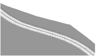
The Roadway (NURBS) tool uses NURBS curves to define the road shape. However, the Roadway (NURBS) object does not represent accurate alignments of low-speed roadways, which are typically constructed with arcs (constant radius) and tangents (straight lines); use the Roadway (Poly) tool for this.
NURBS roadways can also be created by drawing a closed 2D shape and then selecting the Create Objects from Shapes command (see Creating objects from shapes).
Here is a suggested process for creating a NURBS roadway:
Create the roadway.
Select the Send to Surface command to set the road to the existing terrain.
Select Redistribute and Smooth Curve from the Object Info palette of the selected roadway once or twice to smooth out the road slightly, so it does not follow every hill and valley in the existing terrain.
Manually reshape the road in 3D as required (to match other road elevations, garage elevations, and so on).
Only select Redistribute Stations for more or fewer station annotations. Fewer stations are easier to work with when sketching and reshaping, but a road construction company might require more stations to be specified. Redistribute Stations is also useful to ensure that the station spacing is equal after reshaping the road.
To create a road with the Roadway (NURBS) object:
Click the tool and mode.
Multiple roadway tools share the same position on the tool set. Click and hold the mouse on the visible tool to open the Pop-out tools list and select the desired tool.
See Creating NURBS curves for information on which mode to select.
Click in the drawing file to set the start point of the road, and then click to set the position of each additional NURBS vertex. Double-click the last point to complete creation of the roadway (NURBS) object.
The first time you use the tool in a file, a properties dialog box opens. Set the default parameters. The parameters can be edited later from the Object Info palette.
Click to show/hide the parameters.Click to show/hide the parameters.
|
Parameter |
Description |
|
Z height |
Adjusts the elevation of the entire road |
|
Rotation |
Specifies the number of degrees to rotate the object (0.00 is horizontal) |
|
Text Style |
Select a text style from a library or the current file. To use the style defined for the object’s class, select <Class Text Style>. To format the text using options on the Text menu, select <Un-Styled>. See Using text styles and Formatting text. |
|
Road Length |
Displays the length of the road |
|
Paving Width |
Specifies the overall width of the paved road surface (without curbs) |
|
Paving Height |
Specifies the road paving thickness (without curbs) |
|
Curb Width |
Specifies the curb or shoulder width |
|
Curb Height |
Specifies the curb or shoulder height |
|
Left Guardrail |
Adds a guardrail to the left side of the road |
|
Right Guardrail |
Adds a guardrail to the right side of the road |
|
Show Stations |
Displays the station points (the NURBS curve vertices). In 2D, stations display as loci with text displaying the point elevation. In 3D, the stations display as round stakes. |
|
Create Pad for Site Model |
Creates a pad modifier for the Roadway (NURBS) object |
|
Create Grade Limits for Site Model |
Creates a grade limits modifier for the Roadway (NURBS) object, to control the zone where the terrain transitions between the existing elevation and the road elevation |
|
Grade Limits Method |
Specify whether to create offset or sloped grade limits |
|
Grade Limits Off. |
When creating offset grade limits, specify the distance from the road to the grade limits |
|
Grade Limits Slope |
When creating sloped grade limits, specify the batter slope |
|
Paving/Curb Class |
To control appearance and visibility, select a class for each category of roadway geometry from the list of classes present in the drawing, or create a new class. Select <Roadway (NURBS) Class> to place the component attributes in the same class as the roadway object. |
|
Redistribute Stations |
Redistributes the stations at a specified spacing interval |
|
Redistribute and Smooth Curve |
Redistributes the station points at a specified spacing interval and smooths the NURBS curve |
|
Click to set the Z value of the stations to the surface of the site model. The stations can be set to either the surface of the existing site model, or to the surface of the proposed site model, which may have been altered by modifiers. If the stations are sent to the surface of a proposed site model which has been changed by modifiers, it may be necessary to deselect Create Pad for Site Model and Create Grade Limits for Site Model for the Roadway (NURBS) in order to prevent site modifier errors caused by crossing pads or grade limits. |
|
|
Sets the elevation of the indicated station points to a specific plane. As the starting and ending stations are indicated, a red line previews the included station points. The % Grade indicates the grade that will be set between station points. |
|
|
NURBS curve parameters |
Edits the roadway NURBS curve |
If necessary, use the Reshape tool to modify the locations of the vertices after object creation, or use the vertex editing controls from the Object Info palette to move the vertices or change the degree of vertices.
Update the site model. Select the site model and click Update from the Object Info palette.

