Creating framing members
|
Mode |
Tool |
Tool set |
|
Modes for Creating lines |
Framing Member
|
Detailing |
The Framing Member tool draws framing elements for rafters, beams, joists, and framing members with a horizontal projection.
For a file created in a version of Vectorworks Architect prior to 2009, board, joist, rafter, and original framing member objects are considered to be “legacy” objects. To convert them to the current functionality of the framing member tool, select Tools > Utilities > Update Plug-in Objects; see Migrating from previous versions.
To create a framing member:
Click the tool and mode.
Click to place the object in the drawing, and click again to set the length and rotation. The first time you use the tool in a file, a properties dialog box opens. Set the default parameters. The parameters can be edited later from the Object Info palette.
The starting point and direction in which the framing member is drawn determine which end is which. When a single framing member object is selected in Top/Plan view, a blue arrow is placed at the starting point and indicates the object’s direction.
![]()
Click to show/hide the parameters.Click to show/hide the parameters.
|
Parameter |
Description |
|
Rotation |
Specifies the angle of the framing member object |
|
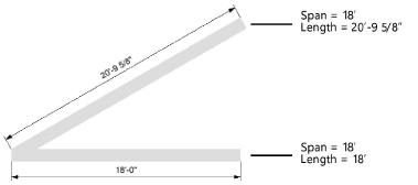
Span |
Specifies the horizontal projection of the framing member in the floor plan; for rafters, specifies the horizontal distance from the inside surface of the supporting wall to the inside surface of the ridge board.
The Span, Length, and Pitch parameters are interdependent and are automatically calculated. When the span value is changed, the length is recalculated; the pitch remains fixed. |
|
Length |
Specifies the length of the framing member When the length value is changed, the pitch is recalculated; the span remains fixed. |
|
Width |
Indicates the framing member profile width |
|
Height |
Sets the framing member profile height |
|
Type |
Select the form of framing element: rafter, solid beam, wood floor truss, open-web steel joint, cold-formed steel channel, steel section, or custom profile |
|
Provides a label describing how the framing member is used. To specify your own structural use name, click Other. The Enter Special Structural Use dialog box opens; enter text for the structural use of this framing member. |
|
|
Select the framing member’s building material. Select Default to use the material implied by the framing member Type, when the selected type indicates a material (for example Steel Section). To add a material to the list, click Other. The Add New Material dialog box opens; enter the new material. The addition is saved with the document. |
|
|
Volume |
Displays the calculated volume of the framing member |
|
Volume Units |
Select the units for calculating the framing member volume: board feet, cubic feet, cubic meters, or the default volume units set for the file (see Units) |
|
Quantity Label |
Describes the standard material size required for the specified framing member, for use in quantity worksheets. When there is no standard material size that accommodates a specified measurement, the label displays a ?. You can edit the Lumber Sizes.txt file (located in the Vectorworks application folder [Vectorworks]\Plug-ins\VW_Arch\Data) to add material sizes that are available in your locale. Restart the software after editing the text file for the changes to take effect. |
|
Pitch |
Specifies the slope of the framing member along its span. When the pitch value is changed, the length is recalculated; the span remains fixed. |
|
Lock End on Resize |
For framing members with a non-zero Pitch, resizes the member from its start point, instead of its end point |
|
Beginning/Ending miter |
Specifies the miter angle at each end of the framing member. This is the angle that the framing member is cut, in plan. |
|
Beginning/Ending bevel |
Specifies the bevel angle at each end of the framing member. This is the angle that the framing member is cut, in elevation. |
|
2D Display |
Select the 2D display method for the framing member: solid, centerline, width, or width with centerline |
|
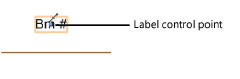
Show Label |
Displays the text entered in Label Text as a label next to the 2D representation of the framing member. After placement, adjust the text position with the control point.
|
|
Label Text |
Enter the text to display in 2D as a label |
|
If you change the vertical reference from top, center, or bottom, the Change Vertical Reference dialog box opens; if the object position is maintained, the framing member remains stationary and the placement line is adjusted. If the defining line is maintained, the framing member object moves accordingly. |
|
|
Rafter |
|
|
Bearing inset |
Specifies the offset distance of the framing member’s bearing point (insertion point) from its end |
|
Overhang |
Specifies the additional length that the framing member extends past its end |
|
Eave Style |
Select vertical, horizontal, double, or square eave profile |
|
Fascia Height |
For double eave styles, specifies the height of the end of the framing member profile |
|
Upper Notch Offset/Depth |
Indicates the size of an optional notch located at the top of the framing member |
|
Solid Beam |
|
|
Draw 2D Hangers |
Displays 2D graphics indicating framing hangers at start, end, both, or none |
|
Roll Angle |
Specifies the angle the framing member rotates about its cross-section axes |
|
Wood Floor Truss |
|
|
Draw 2D Hangers |
Displays 2D graphics indicating framing hangers at start, end, both, or none |
|
Flange Height |
Sets the height of the truss top and bottom chords; the chord width is set by the object width |
|
Web Width/Height |
Specifies the size of the truss web components; if Use Solid Web is selected, the Web Width parameter specifies the thickness of the solid web |
|
Panel Spacing |
Indicates the spacing of the truss “panels” (subdivisions) |
|
Draw Verticals |
Displays vertical web components between each sloping web component |
|
Has Opening |
For “open-web” trusses, inserts an opening between the web components at the mid-point of the truss |
|
Use Solid Web |
Toggles the web component configuration between “open-web” and solid, “I-beam” style |
|
Open-Web Steel Joist |
|
|
Flange Height |
Sets the height of the truss top and bottom chords; the chord width is set by the object width |
|
Web Width/Height |
Specifies the size of the truss web components |
|
Gauge |
Sets the thickness of the top and bottom chords |
|
Panel Spacing |
Indicates the spacing of the truss “panels” (subdivisions) |
|
Draw Verticals |
Displays vertical web components between each sloping web component |
|
Bottom Bearing |
Toggles the configuration of the truss between top chord and bottom chord bearing |
|
Cold-formed Steel Channel |
|
|
Draw 2D Hangers |
Displays 2D graphics indicating framing hangers at start, end, both, or none |
|
Flange Height |
Specifies the length of the top and bottom flange extensions |
|
Gauge |
Sets the thickness of the framing member |
|
Roll Angle |
Specifies the angle the framing member rotates about its cross-section axes |
|
Steel Section |
|
|
Roll Angle |
Specifies the angle the framing member rotates about its cross-section axes |
|
The Select Structural Shape dialog box opens. Select the structural shape and the shape’s series and size. |
|
|
Structural Shape data |
Displays the selected structural shape symbol name, series, and size |
|
Custom Profile |
|
|
Profile Symbol Def |
Displays the selected profile symbol name |
|
The Choose a Symbol dialog box opens. Click the symbol selector. From the Resource Selector, double-click a profile symbol to apply it. The profile symbol definition displays in the Object Info palette. |
|
|
Roll Angle |
Specifies the angle the framing member rotates about its cross-section axes |