 Structural member settings
Structural member properties can be set in the Structural Member Settings dialog box before the structural member object is inserted in the drawing; access it by clicking the Structural Member tool and then clicking the Preferences button from the Tool bar. These preferences serve as the new default for structural members inserted in the drawing until the preferences are changed.
To set the structural member settings:
Click the Profile tab and set the parameters. The Member graphic reflects the Member Type but not the shape.
Click to show/hide the parameters.Click to show/hide the parameters.
Click the Geometry tab and set the parameters. The alignment graphic indicates where the Axis Alignment point is located.
Click to show/hide the parameters.Click to show/hide the parameters.
|
Parameter |
Description |
|
Alignment |
All associations and end conditions are based on the centerline that controls 2D/3D representations; the alignment can be shifted to allow accurate placement of the member |
|
Profile Rotation |
Specifies an angle to rotate the structural profile about the member’s centerline axis |
|
Axis Alignment |
Select the axis alignment |
|
Offset Y’/Z’ |
Enter the offset, if needed |
|
Elevation |
The elevation of the start and end points can be explicitly set, in reference to the story or layer |
|
Start/End Bound |
Select the reference for the start/end point. The elevation start and end bounds must be set separately for Column Insertion mode than for Linear Insertion and Poly Insertion modes. |
|
Start/End Offset |
Enter the start/end offset, if needed |
|
Start and End Conditions |
The offset, miter, and bevel of an end can be set manually or automatically derived from an associated structural member. Values entered for associated members apply as an addition to the automatically determined values. |
|
Start/End Condition |
Select whether to set the start/end conditions automatically by association, manually (custom), or to snap them to horizontal or vertical. |
|
Start/End Offset |
Set the offset, if needed to establish clean member connections; the offset is the distance to the end of the member geometry from the end of the centerline curve |
|
Start/End Miter |
Set a start/end miter angle of 70° or less |
|
Start/End Bevel |
Set a start/end bevel angle of 70° or less |
Click the 2D Attributes tab and set the parameters.
Click to show/hide the parameters.Click to show/hide the parameters.
|
Parameter |
Description |
|
Set Attributes By |
Select whether to set attributes for the object in the Attributes palette, or by class, by line style, or by material (if a material is used). Fills and line color may not be supported for line style. |
|
Above/At/Below Cut Plane |
If attributes are set by class or line style, set the attributes for the structural member. Structural members show uniform 2D attributes for the entire object, unlike other objects which can show separate attributes at the cut plane elevation. The 2D attributes are determined by the attributes applied in the Structural Member Settings dialog box and the cut plane elevation, which is set either in the Object Info palette or by the design layer’s cut plane elevation. |
|
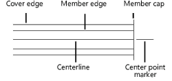
Use Center Mark |
Displays a center point marker at the end of the member; set the length of the marker and size of the gap, if needed. If attributes are set by class or line style, set the attributes. |
|
Caps |
Displays start and/or end caps for the member When the cap is turned off for an end that is associated with the edge of another member, a gap is drawn in the edge of the connected member |
Click the 3D Attributes tab and set the parameters.
Click to show/hide the parameters.Click to show/hide the parameters.
|
Parameter |
Description |
|
Set Attributes By |
Select whether to set attributes for the member and the cover in the Attributes palette, or by class or by material (if a material is used) |
