 Displaying individual 3D objects in section viewports
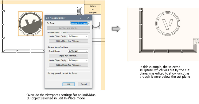
You can override the default cut plane, display, and attributes for individual 3D objects in a specific section viewport. This can be done only by selecting the object within the viewport’s Edit In-Place mode. These settings apply only to selected objects as displayed within the current viewport and do not affect the appearance of the model itself or of other viewports in the drawing.

To set the appearance of an individual 3D object viewed in a section viewport:
Right-click on the section viewport and select Edit Section in Place from the context menu.
In Edit In-Place mode, select one or more eligible 3D objects to assign the same cut plane and display parameters.
When objects below or beyond the cut plane are not displayed with the current viewport settings, X-ray Select mode allows hidden objects to be visible and selected, while in Edit In-Place mode. X-Ray Select mode does not help visualize objects above or before the cut plane.
Click Cut Plane and Display from the Object Info palette, and set the parameters in the Cut Plane and Display dialog box.
Click to show/hide the parameters.Click to show/hide the parameters.
|
Parameter |
Description |
|
Cut Plane |
Select the method for controlling the cut plane for the selected objects. Object Setting: Displays the object according to the symbol definition’s or plug-in object’s/style’s Horizontal/Vertical Section Cut Plane setting (see Creating symbol definitions and Setting the section cut plane display for plug-in objects). If all selected objects have the same setting, the setting displays in parentheses. By Viewport: Displays cut plane graphics and extents as they are defined for the current viewport. Custom: Makes Cut Plane and Extents available for selection, to provide custom settings for the selected objects (available for horizontal section viewports only). View as Uncut beyond/below: Displays the selected objects uncut as though located beyond/below the cut plane. View as Uncut before/above: Displays the selected objects uncut as though located before/above the cut plane. |
|
Cut Planes and Extents (Horizontal section viewports only) |
Opens the Cut Planes and Extents dialog box; see Setting horizontal section viewport cut planes and extents |
|
Extents beyond/below/before/above Cut Plane |
When the viewport is set to display objects beyond/below and before/above the cut plane, sets whether and how to display the selected objects |
|
Hidden Object/Object Display |
Select the method for controlling the display of the selected objects. By Viewport displays the objects as they are defined for the current viewport. None excludes the objects from the view. Hidden Line/Dashed Hidden Line allows you to specify the pen attributes for the objects. |
|
Object/Hidden Object Pen Attributes |
Click to open the Object Display or Hidden Object Display dialog box and set pen attributes for the selected objects; see Object/hidden object display and pen attributes in section viewports |
