 Analyzing cable paths
The Analyze Cable Routes command and the Edit Cabling tool assist with fine tuning the cable route design, integrating the schematic design with the cable path, and identifying errors that need correction.
Analyzing the cable route
|
Command |
Path |
|
Analyze Cable Routes |
ConnectCAD > Documentation |
This command analyzes the cable path network and assigns each circuit from the schematic to a cable path segment.
This command does not assign circuits to cables placed with the Cable tool. To do this, provide a Run ID in the cable's Object Info palette. On the schematic layer, select the circuit to be assigned, and in the circuit's Object Info palette, select the same Cable from the list to assign the cable to the circuit.
This command excludes cable routes to and from external connections when the circuits have <EXT> in the name.
To analyze the cable routes:
Select the command.
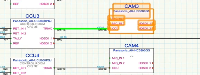
If the analysis is successful, every circuit object in the schematic is associated with a cable path segment. If there are circuits which cannot be associated with the cable path, an error message displays. If the problems are expected—for example, a camera has not yet been attached to the cable path network or to a drop point, or the routing is so obvious that the detailed cable paths weren't necessary—proceed with the design and make the connection later, or not at all. Otherwise, click Mark up Circuits to highlight the circuits which could not be assigned to a cable path, and correct any errors.

The circuit highlighted in green could not be assigned to a cable segment. Correct the problem by attaching the camera to the cable network with the Cable Route tool.
Analyzing a cable segment
|
Tool |
Tool set |
|
Edit Cabling
|
Cable Route |
This tool displays a list of all the circuits that pass through a particular segment of a cable path.
The tool is also used to create pre-cabling circuits for the Spare Cabling layer. See Pre-cabling the model.
To determine the circuits associated with a cable path segment:
Select the tool.
Click on the cable route segment to analyze.
If the cable route has not yet been analyzed with the Analyze Cable Routes command, this analysis occurs automatically to verify the existence of a route for each circuit.
The Edit Cabling dialog box opens, displaying the list of circuits that are associated with the cable path segment. Each distinct circuit's parameters display, along with a temporary Route Index number. Sort the circuits by Route Index to see which circuits share the same path.
In addition to circuits, cables inserted by the Cable tool that are associated with the cable path segment display in the list. The Circuit column entry for these cables is blank.
Double-click on a row in the list to highlight the entire route taken by the selected circuit. The drawing pans and zooms temporarily to show the route.
