Dimensioning exterior walls
|
Command |
Workspace: Path |
|
Dimension Exterior Walls |
Architect: AEC Landmark: Landmark > Architectural Spotlight: Spotlight > Architectural |
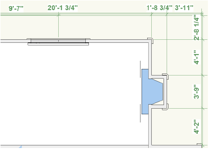
The exterior walls of a building can be automatically dimensioned with the Dimension Exterior Walls command. The command can:
Dimension relative to either walls or core components.
Dimension along either outer sides or centerlines of the walls or core components.
Associate the dimensions with the wall geometry.
Dimension only visible wall components.
Dimension windows and doors either to the center or the edges of the wall opening.
For window objects, the rough opening is calculated as the unit size plus two times the shim gap. For door objects, the rough opening is calculated as the leaf size plus two times the jamb width plus two times the shim gap.
The exterior wall dimensioner uses the dimension standard specified on the Dimensions tab of the document preferences (File > Document Settings > Document Preferences) and the unit selection and precision settings in File > Document Settings > Units.
To generate exterior wall dimensions:
In a file with exterior walls, determine whether you wish to dimension to the structural or non-structural components of the wall. To dimension to the structural components, such as framing components, make the classes of the non-structural components invisible.
The wall styles available in the Vectorworks Architect product contain pre-classed components, making it easy to show and hide the desired portions of the wall.
Select the command.
The Dimension Exterior Walls dialog box opens. Specify how to dimension the walls.
Click to show/hide the parameters.Click to show/hide the parameters.
|
Parameter |
Description |
|
Source Layer |
Specifies the location of the walls to be dimensioned |
|
Options |
Specify the dimension methods |
|
Dimension T-joins in exterior walls |
Interior walls which intersect with the exterior walls are dimensioned |
|
Make dimensions associative |
Associates dimensions with the wall or wall component; dimensions move and update with the wall or wall component |
|
Dimension Relative to |
Specifies whether to dimension relative to the walls or the core components |
|
Dimension to |
Specifies whether to dimension to the outer sides or centerlines of the walls or core components |
|
Dimension to Openings |
Specifies whether to dimension to the center or edges of openings Rough openings are automatically defined in door and window objects. To add a rough opening to a symbol inserted in a wall, draw an invisible polygon (line weight 0, no fill) with three vertices to the extents of the rough opening. |
|
Text Options |
Specifies dimension text properties |
|
Rotation |
Controls the orientation of the dimension text Horizontal keeps text always horizontal Aligned places text according to the dimension angle Horiz/Vert places text horizontally for horizontal dimensions and vertically for vertical dimensions |
|
Location |
Specifies whether the text should be centered between the witness lines if space permits, or always placed outside the witness lines |
|
If forced outside, distance |
Indicates the offset for text forced outside the witness lines |
|
Above Dim Line |
Always places text above the dimension line |
|
Offsets from Building |
Specifies the distance of the dimensions from the building, walls, doors, and windows |
|
Small Dimensions |
Specifies the limit for drawing small dimensions, which can help detect inaccuracies in the drawing; dimensions less than the value specified will be considered “small.” Select Draw in red to detect problems such as minute misalignments in layout; to overlook any inaccuracies, select Do not draw. |
The exterior wall dimensions are drawn automatically.