Inserting a blended screen and projector
|
Tool |
Tool set |
|
Blended Screen
|
Event Design |

The blended screen simulates projection screens that require multiple projectors to produce one large image.

|
Mode |
Description |
|
Modes for the Symbol Insertion tool |
See The Symbol Insertion tool for parameter descriptions |
|
Preferences
|
Sets the default properties for blended screen objects |
|
Place Screen
|
Places and rotates the screen; the projectors can be added after placement |
|
Place Screen and Projector
|
Places and rotates the screen and projectors |
|
Screen Trim Height |
Sets the Z value of the screen at insertion |

To insert a blended screen and projectors:
Click the tool and the symbol insertion and alignment modes.
Enter the Screen Trim Height value on the Tool bar.
Insert the object in the drawing.
In Place Screen mode, click to place the screen, and click again to set the rotation.
In Place Screen and Projector mode, click to place the screen, click again to set the screen rotation, and click again to place the projectors. This is especially useful when placing blended screens and projectors on rigging objects.
The first time you use the tool in a file, a properties dialog box opens. Set the default parameters. The parameters can be edited later from the Object Info palette.
When you use Place Screen mode to insert a blended screen, a Blended Screen object is created. Once the parameters of the blended screen and projectors have been set, click Insert Projectors from the Object Info palette to create the projectors associated with that screen. The blended screen settings control the initial projector settings, though each projector can then be set independently (by changing parameters like text position or cone display) if needed. Moving or rotating a blended screen after the projectors have been inserted also moves or rotates the associated projectors.
If projectors have already been inserted, clicking Insert Projectors deletes existing projectors and their parameter settings.
The height of the blended screen and associated projectors depends on several factors.
The Z value determines the distance from the active layer plane to the bottom of the screen (including the border).
When the screen includes legs, the legs are drawn on the active layer plane unless a Floor Height value has been specified. The Floor Height distance shifts the floor, and therefore the legs, by that amount from the layer plane.
Projector stands are inserted relative to both the Vertical Shift and Floor Height values, allowing stands to be shifted up or down from the screen’s floor as set by the Floor Height value.
In Top/Plan view, when one of the blended screen components, either the screen or the projectors, is placed on a rigging object, that component assumes the height of the rigging object and associates with it. In a 3D view, the height is determined by the component’s insertion point on the rigging object. The Manage Loads tool allows precise repositioning of the blended screen components; see Managing loads.
Blended screen parameters
Click to show/hide the parameters.Click to show/hide the parameters.
|
Parameter |
Description |
|
Screen Type |
Select either front or rear projector |
|
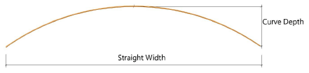
Curved |
Select the option when the blended screen is curved, and specify the additional Straight Width and Curve Depth parameters
|
|
Name |
Provide a name for the screen object; associated blended projectors identify the screen by this name; if the name is already in use, the name that was already in use changes automatically |
|
Width (image) |
Enter the width of the screen image area (without the screen border or frame) |
|
Straight Width (Curved screen) |
Sets the width of the screen from the start of the arc to the end of the arc |
|
Curve Depth (Curved screen) |
Specifies the depth of the screen from the front edge to the back edge |
|
Height (image) |
Enter the height of the screen image area (without the screen border or frame) |
|
Size (pixels) |
Displays the total screen size based on the screen dimensions |
|
Frame |
Select the type of border around the image area: No Frame, a Frame with a specified thickness, or a flat Border Only |
|
Border Widths Top/Bottom/Left/Right |
For Frame and Border Only types, specify the width of the frame or border for each side of the frame or border |
|
Depth |
For Frame type, indicate the thickness of the frame |
|
Edge |
For Frame type, sets the distance between the screen and the front face of the screen’s frame |
|
Tab-Tensioned Sides |
When the frame type is Border Only and the screen support is Roll-Down Case, this option is available. Select the option to specify that the side support mechanism is tab-tensioned. |
|
Tilt |
When Add Folding Legs is selected, specifies the tilt of the screen in degrees. Positive values tilt the top of the screen away from the viewer, and negative values tilt it toward the viewer. |
|
Total Clearance |
Displays the total vertical clearance height required by the complete blended screen object from the floor to the top of the screen, including any border, dress kit, valance, or other accessories |
|
Aspect (calc) |
Displays the aspect ratio of the screen |
|
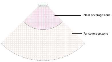
Show Coverage Zone (2D only) |
Indicates the viewing area based on the screen size; observers within the area should be able to see the screen
|
|
Zone Reference |
Calculates the coverage zone based on screen width, height, or diagonal measurement |
|
Max Horiz. Angle/ Max Vert. Angle |
Indicates the maximum viewing angle of the screen, horizontally and vertically, relative to dead-on |
|
Viewing Height |
Enter the height of the average viewer when watching (likely, a seated height) |
|
Near Multiplier |
Specifies the multiplier of the reference dimension to determine the extent of the near coverage zone |
|
Far Multiplier |
Specifies the multiplier of the reference dimension to determine the extent of the far coverage zone |
|
Screen Support |
Select the type of screen support: None, Goalpost Legs (includes two legs, and is similar to commercial “fastfold” systems), or Roll-Down Case |
|
Show Feet |
For Goalpost Legs, select how the feet of the frame display: Both, Front, Back, or None |
|
Depth |
For Roll-Down Case support, specifies the size of the case drawn at the top (roll-down case) or bottom (roll-up case) of the video screen; the case length is determined by the screen size |
|
Motor |
For Roll-Down Case support, adds space to the case for the motor; select whether the motor is located on the right or the left |
|
Opening |
For Roll-Down Case support, sets the location on the case where the screen exits the case; select Front, Center, or Back |
|
Add Dress Kit |
When goalpost legs are selected, adds a “dress kit” of draperies to conceal the projector (rear) and supports from audience view |
|
Dress Kit Color |
Select the color of the dress kit draperies |
|
Left Leg Width |
Indicates the width of the drapery on the left side of the screen |
|
Right Leg Width |
Indicates the width of the drapery on the right side of the screen |
|
Valance Height |
Sets the height of the drapery above the screen |
|
Border Overlap |
Indicates the amount of overlap of the dress kit drapery over all sides of the screen’s border |
|
Pleat Width |
Specifies the width of each pleated section of the left, right, and valance draperies |
|
Pleat Depth |
Specifies the depth of the pleats for the left, right, and valance draperies |
|
Edit Screen Image |
Opens the Edit Screen Image dialog box |
|
Screen Image |
Displays the name of the current screen image |
|
Projector |
Select the projector model from a library; specify the projector settings, which apply to all projectors upon insertion |
|
Weight |
Enter the weight of the projector |
|
Wattage |
Enter the required wattage, for power consumption calculations and reporting |
|
Aspect |
Select the projector aspect ratio |
|
Resolution |
Select the projector pixel resolution |
|
Overshoot % |
Specifies the total amount of top and bottom overshoot to be discarded when using narrow aspect projectors to achieve a certain pixel blend |
|
Tilt |
Sets the tilt of the projector, in degrees, relative to the horizontal plane |
|
Place Based On |
Sets the position of the projector either based on a fixed lens size or the projection distance |
|
Projection Dist. |
When Distance is selected for the projector placement, enter a distance value or click and drag the projectors in the drawing to set the distance |
|
Lens |
Select a standard fixed or zoom lens size, or choose Custom |
|
Zoom Factor |
For zoom or custom lenses, sets the lens zoom factor |
|
Vertical Position |
Select the projector placement mode: Screen Center: The center of the projector lens aligns with the screen center Align to Top: The top of the projector body aligns with the top of the top of the screen border Align to Bottom: The bottom of the projector body aligns with the bottom of the screen border Stand: Places the projector on a stand selected in Stand Model Rigged: Places the projector at a height specified in Floor Height with the bottom of the projector at the Trim height Specific Shift: Shifts the projector relative to the screen center by the Vertical Shift distance, as measured from the center of the projector lens |
|
Vertical Shift |
For projectors on a stand or with a specific shift, specifies the distance between the floor (as set by the Floor Height) and the stand or projector (this allows stands or projectors to be placed on a plane shifted up or down from the screen) |
|
Stand Model |
For projectors on a stand, select the projector stand model from a library |
|
Floor Height |
For rigged projectors or projectors on a stand, indicates the distance from the active layer plane to the floor, effectively shifting the floor by the indicated height |
|
Trim (bottom) |
For rigged projectors, indicates the location of the bottom of the projector |
|
Multiple Projector |
When there is more than one projector (identical paired projectors for each section of the screen), select whether they are stacked or side-by-side |
|
Horiz Space |
For side-by-side multiple projectors, sets the distance between the projectors |
|
Area Horiz. Count |
Sets the number of areas into which the screen is divided; if the value entered is too small, the lowest possible number of areas is automatically set |
|
Area Width |
Displays the width of each screen area |
|
Area Height |
Displays the height of each screen area |
|
Area Spacing |
Displays the distance between projectors, measured from the center of each projector lens |
|
Overlap (meas.) |
Displays the amount of screen area overlap, measured in distance units |
|
Overlap (pixels) |
Displays the amount of screen area overlap, measured in pixels |
|
Overlap (%) |
Displays the amount of screen area overlap, as a percentage |
|
Blend Reference |
Inserts the projector starting on the projector’s left, right, or center |
|
Show Projection Cones |
Toggles the display of the projection cone for all projectors associated with the screen |
|
Note |
Adds a note, which can be placed in the drawing with the Text Options |
|
Insert Projectors |
In Place Screen mode, inserts the required number of blended projectors based on the specified parameters; these projectors are associated with the blended screen. The projector model specified in Projector Model, and its associated parameters, apply to all inserted projectors. |
|
Text Options |
Opens the Text Options dialog box, to enable the display and format the text of labels |
|
Default Text Positions |
Restores text labels to their default positions |
|
Opens the Classes dialog box, to specify class naming for the various portions of the blended screen. This allows portions of the blended screen, projectors, and other elements to be set to visible, grayed, or invisible. Use the standard class, select a class from the list of classes present in the drawing, or create a new class. Select <Blended Screen Class> to place the blended screen element in the same class as the blended screen. Class Prefix: Specifies an optional default root class naming standard for all blended screen parts; click Assign Default Classes With Prefix to begin all blended screen class names with the prefix, so that they are sorted together. Assign Default Classes With Prefix: Sets the class names for all blended screen elements to the standard, using the Class Prefix if there is one. Blended screen elements: For each portion of the blended screen, specifies the class name standard; the class names shown here are applied to the elements. |
|
|
Update |
Updates the blended screen object and its associated projectors when changes have been made to the screen’s Object Info palette parameters; this also refreshes the associated projector information without changing individual blended projector parameters such as text options |
|
Load Information |
A blended screen is considered a distributed load in Braceworks calculations; if the screen is inserted parallel to a rigging object, it is considered to be a load on that structure. Load information is used for Braceworks calculations and reports (Braceworks required). |
|
Include in Calculations (Braceworks required) |
Includes the blended screen in Braceworks calculations; deselect to exclude the object from participating in structural calculations |
|
Load Group Name |
The load category is always Video for blended screen objects |
|
Load ID |
Enter a unique ID for the load for informational use in reports |
|
Load Name |
Identifies the object in load calculations |
|
Distributed Weight |
Enter the distributed weight of the blended screen object; changes here also affect the Total Weight value |
|
Total Weight |
Enter the total weight of the object |
|
Position |
Displays the name of the associated rigging object, if the screen is attached. Optionally, attach this object to a rigging object, or change the rigging object association, by entering the Position Name of the rigging object. Delete the name to break the association. For other methods to attach loads, see Making the attachment. |
Blended projector parameters
Click to show/hide the parameters.Click to show/hide the parameters.
|
Parameter |
Description |
|
Screen Name |
Displays the name of the screen with which the projector is associated |
|
Screen Parameters |
Displays the main screen parameters set by the blended screen |
|
Show Projection Cone |
Toggles the display of the projection cone for this projector only |
|
Projector |
Select the projector model from a library; by default, the projector model specified for the blended screen is selected, but can be overridden for individual blended projectors |
|
Wattage |
Enter the required wattage, for power consumption calculations and reporting |
|
Projector Parameters |
Displays the projector parameters as required by the blended screen |
|
Show Centerline (Area) |
Displays the projector centerline in Top/Plan view |
|
L/R Shift |
For projectors on a stand, shifts the stand to the left or right, relative to the projector |
|
F/B Shift |
For projectors on a stand, shifts the stand to the front or back, relative to the projector |
|
Horiz. Offset Angle |
Displays the angle of offset from the projector to the screen, measured side to side on the horizontal plane and based on the L/R Shift value |
|
Horiz. Offset Perc. |
Displays the angle of offset from the projector to the screen as a percentage |
|
Point at Screen Center |
When a L/R shift has been applied to the projector, rotates the projector body so that the projection remains pointed at the center of the projection cone area |
|
Tilt |
Sets the tilt of the projector, in degrees, relative to the horizontal plane |
|
Place Based On |
Sets the position of the projector either based on a fixed lens size or the projection distance |
|
Proj. Distance (Straight) |
When Distance is selected for the projector placement, enter a distance value or click and drag the projectors on the drawing to set the distance |
|
Proj. Distance (Actual) |
Specifies the distance in 3D from the projector to the screen |
|
Lens |
Select a standard fixed or zoom lens size, or choose Custom |
|
Zoom Factor |
For zoom or custom lenses, sets the lens zoom factor |
|
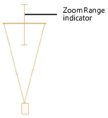
Show Zoom Range (Projector zoom Lens only) |
Indicates the optimal distance from the projector where the screen can be placed, given the zoom range of the lens
|
|
Vertical Position |
Select the projector placement mode: Screen Center: The center of the projector lens aligns with the screen center Align to Top: The top of the projector body aligns with the top of the top of the screen border Align to Bottom: The bottom of the projector body aligns with the bottom of the screen border Stand: Places the projector on a stand selected in Stand Model Rigged: Places the projector at a height specified in Floor Height with the bottom of the projector at the Trim height Specific Shift: Shifts the projector relative to the screen center by the Vertical Shift distance, as measured from the center of the projector lens |
|
Vertical Shift |
For projectors on a stand or with a specific shift, specifies the distance between the floor (as set by the Floor Height) and the stand or projector (this allows stands or projectors to be placed on a plane shifted up or down from the screen) |
|
Stand Model |
For projectors on a stand, select the projector stand model from a library |
|
Floor Height |
For rigged projectors or projectors on a stand, indicates the distance from the active layer plane to the floor, effectively shifting the floor by the indicated height |
|
L/R Shift |
For projectors on a stand, shifts the stand to the left or right, relative to the projector |
|
F/B Shift |
For projectors on a stand, shifts the stand to the front or back, relative to the projector |
|
Trim (bottom) |
For rigged projectors, indicates the location of the bottom of the projector |
|
Vert. Offset Angle |
Displays the vertical offset angle of the projector to the screen, based on the vertical position of the projector |
|
Vert. Offset Perc. |
Displays the vertical offset angle of the projector to the screen as a percentage |
|
Multiple Projector |
When there is more than one projector (identical paired projectors for each section of the screen), select whether they are stacked or side-by-side |
|
Horiz Space |
For side-by-side multiple projectors, sets the distance between the projectors |
|
Note |
Adds a note, which can be placed in the drawing with the Text Options |
|
Text Options |
Opens the Text Options dialog box, to enable the display and format the text of labels |
|
Default Text Positions |
Restores text labels to their default positions |
|
Update |
Updates the object when changes have been made to the Object Info palette parameters |
|
Load Information |
A blended projector is considered a point load in Braceworks calculations; if the insertion point is on a rigging object, it is considered to be a load on that structure. Load information is used for Braceworks calculations and reports (Braceworks required). |
|
Include in Calculations (Braceworks required) |
Includes the blended projector in Braceworks calculations; deselect to exclude it from participating in structural calculations |
|
Load Group Name |
The load category is always Video for blended projector objects |
|
Load ID |
Enter a unique ID for the load for informational use in reports |
|
Load Name |
Identifies the object in load calculations |
|
Total Weight |
Enter the total weight of the object |
|
Position |
Displays the name of the associated rigging object, if the projector is attached. Optionally, attach this object to a rigging object, or change the rigging object association, by entering the Position Name of the rigging object. Delete the name to break the association. For other methods to attach loads, see Making the attachment. |