Inserting a stage plug
|
Mode |
Tool |
Tool set |
|
Modes for the Polyline tool |
Stage Plug
|
Event Design |

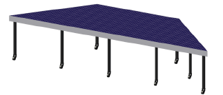
The Stage Plug tool inserts custom shaped stage structures into a drawing. The type, shape, size, and appearance can be customized.
To insert a stage plug:
Click the tool and the creation mode.
Click to set the stage’s start point.
Click to set the end of the segment and the beginning of the next. Continue drawing segments in this manner until the stage object is complete.
The first time you use the tool in a file, a properties dialog box opens. Set the default parameters. The parameters can be edited later from the Object Info palette.
The stage plug can be reshaped with the Reshape tool; see Reshaping objects.
Click to show/hide the parameters.Click to show/hide the parameters.
|
Parameter |
Description |
|
Stage Height |
Specifies the overall stage height |
|
Top Surface Area |
Displays the calculated surface area of the stage |
|
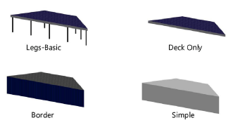
Structure |
Select the type of stage construction
|
|
Deck Details |
|
|
Top Thickness |
Sets the thickness of the deck. The thickness of the deck cannot be set for Border and Simple stage plug structures. |
|
Top Color/Texture |
Displays the texture or color selected in the 3D Options |
|
Trim Height |
Sets the height of the trim around the stage |
|
Trim Color/Texture |
Displays the texture or color selected in the 3D Options |
|
Leg Details |
|
|
Diameter |
For the Legs-Basic structure type, sets the size of the leg supports |
|
Profile |
For the Legs-Basic structure type, select a round, square, or octagonal leg shape |
|
Color/Texture |
Displays the texture or color selected in the 3D Options |
|
Reference Spacing |
For the Legs-Basic structure type, sets an approximate spacing value for the legs; the exact spacing is determined automatically by evenly dividing the length of the deck |
|
Leg Total |
For the Legs-Basic structure type, displays the number of legs |
|
Add Casters |
For the Legs-Basic structure type, adds casters to the legs to create a rolling platform |
|
Wheel Color/Texture |
Displays the texture or color selected in the 3D Options |
|
Specifies the appearance of applicable deck elements in 3D views. The 3D Options dialog box opens. For each available portion of the stage, either select the color from the Color list, or select Custom Texture and then click the current custom texture to open the Resource Selector; double-click a resource to select it. The Object Info palette displays the color or texture selections in the relevant section. The appearance of Simple stage plugs is set from the Attributes palette. |
|
|
Purpose/Set Cart ID |
Enter information about the stage which can be placed in the drawing with Text Options (does not affect the stage appearance) |
|
Note |
Adds a note, which can be placed in the drawing with the Text Options |
|
Text Options |
Opens the Text Options dialog box, to enable the display and format the text of labels |
|
Default Text Positions |
Restores text labels to their default positions |
|
Opens the Classes dialog box, to specify class naming for the various portions of the stage plug. This allows portions of the stage plug to be set to visible, grayed, or invisible. Use the standard class, select a class from the list of classes present in the drawing, or create a new class. Select <Stage Plug Class> to place the stage plug element in the same class as the stage deck. Class Prefix: Specifies an optional default root class naming standard for all stage plug parts; click Assign Default Classes With Prefix to begin all stage plug class names with the prefix, so that they are sorted together. Assign Default Classes With Prefix: Sets the class names for all stage plug elements to the standard, using the Class Prefix if there is one. Stage plug elements: For each portion of the stage plug, including the loci that represent the stage plug legs in the Deck Only Structure, specifies the class name standard to use; the class names shown here are applied to the elements. |
|
|
Update |
Updates the object when changes have been made to the Object Info palette parameters |