Feature control frame
|
Mode |
Tool |
Tool set |
|
Modes for The Symbol Insertion tool |
Feature Control Frame
|
Dims/Notes |

Multiple annotation tools share the same position on the tool set in some workspaces. Click and hold the mouse on the visible tool to open the Pop-out tools list and select the desired tool.
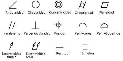
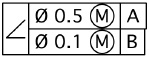
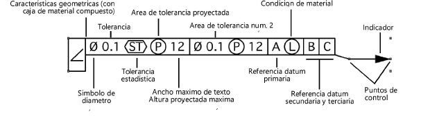
A feature control frame consists of a geometric characteristic symbol, up to two tolerance areas, and up to three datum reference areas.
To insert a feature control frame:
Click the tool and mode.
Click to place the object, and click again to set the rotation. The first time you use the tool in a file, a properties dialog box opens. Set the default parameters. The parameters can be edited later from the Object Info palette.
To add a leader and marker, click the Selection tool from the Basic palette and drag the control points on the object. Edit the marker from the Attributes palette (see Atributos de indicador).
Click to show/hide the parameters.Click to show/hide the parameters.
|
Parameter |
Description |
|
Rotation |
Specifies the number of degrees to rotate the object (0.00 is horizontal) |
|
Text Style |
Select a text style from a library or the current file. To use the style defined for the object’s class, select <Class Text Style>. To format the text using options on the Text menu, select <Un-Styled>. See Using text styles and Formatting text. |
|
Geometric Characteristic |
Select the geometric characteristic symbol, if any
|
|
Composite Box |
Increases the size of the geometric characteristic box; this is used when placing a second feature control frame
|
|
Tolerance Area #1/#2 |
Includes Tolerance Area #1 and/or Tolerance Area #2 |
|
Tolerance |
Enter the tolerance value |
|
Show Diameter Symbol |
Displays a diameter symbol along with the tolerance value
|
|
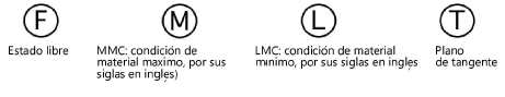
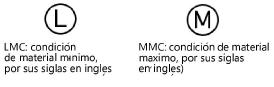
Material Condition |
Choose the material condition, if any
|
|
Statistical Tolerance |
Displays a statistical tolerance symbol
|
|
Projected Tolerance Zone |
Displays a projected tolerance zone symbol |
|
Zone Height |
Enter the maximum projected tolerance zone height when a projected tolerance zone symbol is displayed |
|
Place the PTZ symbol outside the FCF |
Places the projected tolerance zone symbol outside and to the bottom of the feature control frame
|
|
Primary/Secondary/Tertiary Datum Reference |
Includes the primary, secondary, and/or tertiary datum reference |
|
Reference |
Enter the desired reference letter |
|
Material Condition |
Select a material condition, if any
|
|
Leader Position |
Select left or right |