Z-Section
|
Mode |
Tool |
Tool set |
|
Modes for The Symbol Insertion tool |
|
Detailing |
The Z-Section tool and Z-Section - 3D tool share the same position on the tool set. Click and hold the mouse on the visible tool to open the Pop-out tools list and select the desired tool.
To create a Z-section object:
Click the tool and mode.
Click to place the object in the drawing, and click again to set the rotation. The first time you use the tool in a file, a properties dialog box opens. Set the default parameters. The parameters can be edited later from the Object Info palette.
Click to show/hide the parameters.Click to show/hide the parameters.
|
Parameter |
Description |
|
Series |
Select the desired series to display the appropriate nominal sizes |
|
Size |
Select the Z-section size |
|
Length (3D only) |
Enter the length of the 3D Z-section |
|
Place Locus at Centroid (2D only) |
Select whether to draw a locus at the centroid of the 2D Z-section |
|
Lock Centroid Position |
Locks the centroid position; when locked, the centroid behaves like the object’s insertion point and remains in position if the object’s shape/size/rotation is edited |
|
Custom Size |
Select this option to enable fields for specifying a custom Z-section size |
|
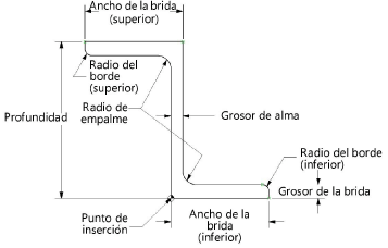
Depth |
Displays the depth between endpoints, or if Custom Size is selected, allows entry of a custom value |
|
Flange Width (Top) / (Bottom) |
Displays the top and bottom flange width, or if Custom Size is selected, allows entry of a custom value |
|
Web Thickness |
Displays the web thickness, or if Custom Size is selected, allows entry of a custom value |
|
Flange Thickness |
Displays the flange thickness, or if Custom Size is selected, allows entry of a custom value |
|
Toe Radius (Top) / (Bottom) |
Displays the top and bottom toe radius value, or if Custom Size is selected, allows entry of a custom value |
|
Fillet Radius |
Displays the fillet radius value, or if Custom Size is selected, allows entry of a custom value |
|
Section Properties |
Section properties are automatically calculated and displayed based on inch units for imperial shapes and millimeter for metric shapes (regardless of the units selected and Show Unit Mark setting in the Units dialog box) |
|
Area |
Displays the Z-section area |
|
About Axis X-X/Y-Y |
|
|
Moment of Inertia |
Displays the moment of inertia about both the horizontal (X-X) and vertical (Y-Y) centroidal axes |
|
Section Modulus |
Displays the section modulus about both the horizontal (X-X) and vertical (Y-Y) centroidal axes |
|
Radius of Gyration |
Displays the radius of gyration about both the horizontal (X-X) and vertical (Y-Y) centroidal axes |