Fillet welding symbol
|
Mode |
Tool |
Workspace: Tool set |
|
Modes for The Symbol Insertion tool |
Welding Sym-Fillet
|
Architect and Spotlight: Dims/Notes Landmark: Add tool to workspace |

Multiple welding tools share the same position on the tool set. Click and hold the mouse on the visible tool to open the Pop-out tools list and select the desired tool.
To insert a fillet welding symbol:
Click the tool and mode.
Click to place the object in the drawing, and click again to set the rotation. The first time you use the tool in a file, a properties dialog box opens. Set the default parameters. The parameters can be edited later from the Object Info palette.
Once the object has been placed, its marker can be selected from the Attributes palette (see Marker attributes).
Click to show/hide the parameters.Click to show/hide the parameters.
|
Parameter |
Description |
|
|
Rotation |
Specifies the number of degrees to rotate the object (0.00 is horizontal) |
|
|
Text Style |
Select a text style from a library or the current file. To use the style defined for the object’s class, select <Class Text Style>. To format the text using options on the Text menu, select <Un-Styled>. See Using text styles and Formatting text. |
|
|
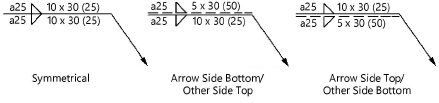
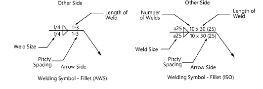
Symmetrical (both sides the same as Arrow Side) (AWS only) |
Reflects the same information on both the arrow side and the other side |
|
|
Configuration (ISO only) |
Select the data display configuration; if symmetrical is selected, the data on the other side is identical to the arrow side
|
|
|
Arrow Side/Other Side |
Select to display data on the arrow side, other side or both; if symmetrical is selected, the displayed data applies to both sides |
|
|
Weld Size |
Displays the size of the weld |
|
|
Number of Welds (ISO only) |
Displays the number of welds |
|
|
Length of Weld |
Displays the length of the weld |
|
|
Pitch/Spacing |
Displays the pitch or spacing of the weld |
|
|
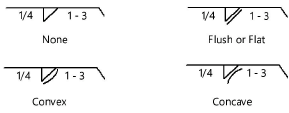
Finish Contour |
Select the finish contour type
|
|
|
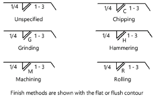
Finish Method |
Select the finish method type. A finish contour must be selected in order to display a finish method.
|
|
|
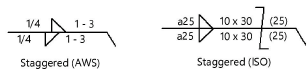
Stagger |
Indicates staggered welds
|
|
|
Arrow |
Sets whether to have an arrow on the leader line |
|
|
Position |
Select the side from which the arrow on the leader line extends (left or right) |
|
|
Reference |
Specify whether to include a reference note |
|
|
Position |
Select the position of the reference note; by default, Left is selected if the arrow is on the right, or Right is selected if the arrow is on the left |
|
|
Ref. Line 1 |
If desired, enter the data to display in the first reference line |
|
|
Ref. Line 2 |
If desired, enter the data to display in the second reference line |
|
|
Ref. Line 3 |
If desired, enter the data to display in the third reference line |
|
|
Weld All Around |
Places a weld all around the marker |
|
|
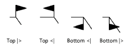
Field Weld |
Places a field weld flag |
|
|
Position |
Sets the position of the field weld flag. Select Top |> to have the flag on top facing right, Top <| to have the flag on top facing left, Bottom |> to have the flag on bottom facing right, Bottom <| to have the flag on bottom facing left.
|
|