 Connecting rigging objects
Inserting specific connections and stacking rigging objects
|
Tool |
Tool set |
|
Insert Connection
|
Rigging |

The Insert Connection tool either connects rigging objects with a drop or stacks them with a truss cross connection. When stacking rigging objects, you can choose to move the object to be stacked either up or down, and select which object to move to bring the rigging objects into parallel alignment, if needed.

|
Mode |
Description |
|
Insert Drop
|
Creates a connection between two rigging objects by placing a dead hang bridle or a hoist at the clicked point |
|
Place Rigging Object on Top
|
Stacks a rigging object above another one, moving a truss and all its associated supports and loads on top of the reference truss. A truss cross is created at the connection point. |
|
Place Rigging Object Below
|
Stacks a rigging object under another one, moving a truss and all its associated supports and loads below the reference truss. A truss cross is created at the connection point. |
|
Preferences
|
Opens the Connection Options dialog box to specify the drop type for Insert Drop mode, and to select the connection symbol for all of the insertion modes |
|
Enable Vertical Offset
|
Toggles the offset insertion on and off |
|
Offset |
If Enable Vertical Offset is on, adds the specified distance between the top truss and bottom truss. For rigging objects connected with drops, the truss to move adjusts to meet the specified offset distance. To change the offset value, see Changing the trim height of a system. For rigging objects connected with truss crosses, the offset value is added to a default distance of 0” between trusses. The Offset can be edited from the Object Info palette of the selected truss cross object. |


Connecting rigging objects with drops
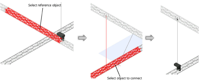
To connect structural elements with one or more drops:
Click the tool, and then click Insert Drop mode.
If an offset is needed, enter the Offset value and toggle Enable Vertical Offset on.
Click Preferences to open the Connection Options dialog box. Select whether to insert the drop as a dead hang bridle or a hoist; if inserted as a hoist, from the Resource Selector, select the hoist symbol for the drop.
Click on the reference rigging object; this truss does not move.
Click on the rigging object to move either up or down (stacking the moved truss below or above).
Valid rigging objects are highlighted, and a preview of the drop location displays.
Click to place the drop at that location and connect the rigging objects.
If the trusses to be connected require adjustment to be stacked in a parallel alignment, the Move Parallel Trusses for Drop dialog box opens. Select whether to move the top truss system (the one with the higher Z value) or the bottom truss system into correct alignment. The selected item is moved.
The selected hoist is inserted.
Connecting rigging objects with a truss cross
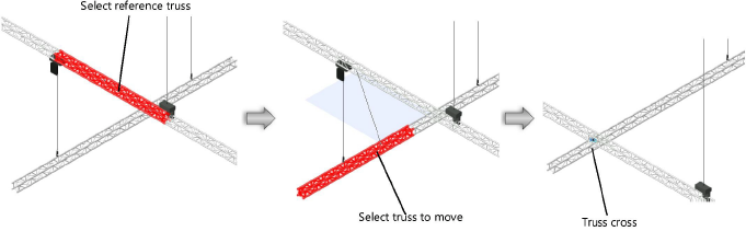
To connect rigging objects to each other with a truss cross:
Click the tool, and then, depending on whether you want to stack a truss above or below another one, click either Place Rigging Object on Top or Place Rigging Object Below mode.
If an offset is needed, enter the Offset value and toggle Enable Vertical Offset on.
Click Preferences to open the Connection Options dialog box; select whether to use a symbol for the truss cross, and if so, from the Resource Selector, select a truss cross symbol.
Click on the reference truss; this truss does not move.
Click on the truss to move (stacking the moved truss above or below the reference truss).
The truss is stacked with the reference truss, and any connected hoists, attached loads, and supports move with the truss. If hoists are connected between the trusses, they are removed; hoists connected to other truss sections may be lengthened or shortened.
A truss cross is created at the connection point. A truss cross indicates how to calculate and model the connection between stacked trusses. Depending on the selected symbol, its appearance indicates the type of connection (whether it is connected, flexible, or rigid; can transmit all forces, or only tension or only compression forces, or no forces). A label indicates the truss cross’s name, type of connection, and the current force.
The truss cross parameters can be edited later from the Object Info palette.
Click to show/hide the parameters.Click to show/hide the parameters.
|
Parameter |
Description |
|
Properties |
|
|
Name |
Enter a truss cross name |
|
Maximum Force |
Specifies the maximum allowable force for the truss cross |
|
Force |
Displays the calculated force (Braceworks required) |
|
Connection Type |
Indicates whether the truss cross is rigid, pliable, or not connected; a truss cross that does not transmit any forces is considered not connected |
|
Transmitted Forces |
Indicates whether the truss cross can transmit all forces, or only tension or compression. Rigid truss crosses always transmit all forces. If the truss cross is not connected, this parameter is not available. |
|
Display |
|
|
Show Symbol |
Display the selected symbol instead of default geometry |
|
Symbol Name |
Displays the name of the selected symbol |
|
Select Symbol |
Opens the Resource Selector to select a resource for placement; double-click a resource to activate it |
|
Offset |
Sets the vertical offset between the top truss and bottom truss; the value can be 0-300 mm (0-11.8 inches). If you change this value from the Object Info palette, you are prompted to select whether to move the top or bottom truss system to apply the new offset. |
|
Opens the Classes dialog box to control appearance and visibility of the truss cross parts; do one of the following: Click Use Standard Classes to set the class names for the truss cross parts to the standard. Select a class from the list of classes present in the drawing, or create a new class. Select <Object Class> to place the part attributes in the same class as the truss cross object. |
|
|
Select similar objects |
|
|
Objects of same name |
Selects truss cross objects with the same Name parameter |
|
Objects of same connection type |
Selects truss cross objects with the same Connection Type parameter |
|
Objects of same transmittable forces |
Selects truss cross objects with the same Transmitted Forces parameter |
