Placing a Renderworks camera
|
Tool |
Tool set |
|
Renderworks Camera
|
Visualization |

The Renderworks Camera tool sets a camera view, and allows you to activate a particular camera, which makes it easy to modify the view. Specific attributes, such as camera focal length, field of view, height, and aspect ratio can be set, as can Renderworks camera effects such as depth of field, exposure, bloom, vignetting, and chromatic aberration when rendering in Final Quality Renderworks or Custom Renderworks render modes.
Several preset Renderworks camera resources, with settings for effects such as daylight or interior low light, are available from the Vectorworks Libraries in the Resource Manager.
To insert a Renderworks camera:
Click the tool.
Click on the design layer to specify the camera location. Click again to indicate the camera’s look-to point. The first time you use the tool in a file, a properties dialog box opens. Set the default parameters. The parameters can be edited later from the Object Info palette.
You can create your own preset camera resources for later use by converting a camera to a symbol with Convert to Group selected in the Create Symbol dialog box (see Creating symbol definitions). On insertion, the symbol is ungrouped and inserted as a Renderworks camera object that can be modified if needed.
Click to show/hide the parameters.Click to show/hide the parameters.
|
Parameter |
Description |
|
Camera Height |
Sets the camera height. If a Z value is also specified for the camera object, the total camera height is the sum of the Z height and the Camera Height. |
|
Look To Height |
Sets the height of the camera look-to point. If a Z value is also specified for the camera object, the total look-to height is the sum of the Z height and the Look To Height. |
|
Top/Plan View |
Switches to a Top/Plan view of the camera |
|
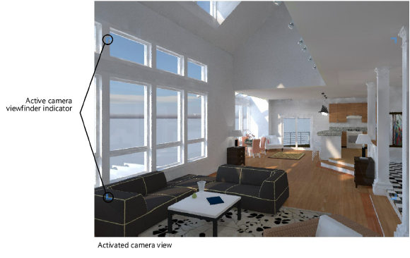
Activate Camera View (appears when no camera is activated) |
Changes the document view to the camera view and displays the active camera viewfinder indicator, links the camera to the current document view so that viewing tools (such as the Flyover and Walkthrough tools) affect the camera, and enables the Renderworks camera effects when rendering in Final Quality Renderworks or Custom Renderworks render modes. The camera can also be activated by double-clicking it with the Selection tool and from the Visualization palette; see Managing lights and cameras with the Visualization palette. Use the multiple view panes feature (see Using multiple drawing views) to view the camera in a third-person view and in first-person camera view simultaneously. When the views are linked, the camera view will update in real time when the Renderworks Camera object is edited. |
|
Deactivate Camera (appears when a camera is activated) |
Unlinks the camera from the current view so that viewing tools do not affect the camera view, removes the active camera viewfinder indicator, and disables the Renderworks camera effects when rendering in Final Quality Renderworks or Custom Renderworks render modes. The camera can also be deactivated by changing the view so the camera is no longer active (for example by switching to Top/Plan view or changing layer visibilities so that the camera’s layer is no longer active) or from the Visualization palette; see Managing lights and cameras with the Visualization palette. |
|
Match Current View |
When in a 3D view, repositions a selected but deactivated camera so that the camera’s new view is identical to the current 3D view. The camera’s location and orientation change to match the current view, but other camera parameters remain unchanged. Alternatively, select a deactivated camera from the Visualization palette, and right-click and select Match Current View from the context menu. |
|
|
Click to aim the selected camera at a selected point on the drawing; the cursor changes to indicate the operation is active. Click on the drawing to aim the camera. |
|
Fine Tune Camera View |
Opens the Perspective View Controls dialog box, for making fine adjustments to the camera view controls (see Adjusting the Renderworks camera view) |
|
Projection |
Select Perspective or Orthogonal projection for the camera view; Perspective creates a cropped or uncropped perspective view of the model from the camera view, while Orthogonal is useful for an elevation view (for example, a skewed elevation view of a building which is not in a standard view). Available parameters depend on the selected projection. |
|
Render Mode |
Select a render mode for the 3D camera view |
|
Aspect Ratio |
Sets the aspect ratio of the perspective clipping window; the clipping window can also be set to the page size or to a custom aspect ratio |
|
Custom Aspect |
When a custom Aspect Ratio is selected, enter the custom ratio |
|
For Film Size of |
Specifies the camera film size, and determines the focal length of the camera (has no effect on the camera view) |
|
Focal Length is |
Displays the camera focal length, based on film size |
|
Field of View |
Specifies the view angle. Use the control point to set the view angle on the 2D camera with the mouse. |
|
For DPI of |
Calculates the pixel size when exporting the camera view (has no effect on the camera view) |
|
Pixel Size is |
Displays the pixel size based on the DPI setting |
|
Crop Frame Scale % |
Scales the size of the clipping window frame, when in a cropped perspective projection, and also scales the perspective distance. As a result, both the crop frame and the drawing appear scaled. |
|
Left/Right Tilt Angle |
Tilts the camera to the left or right, for more accurate perspective matching |
|
Camera Name |
Specifies a name for the camera, which can be displayed or hidden in 2D view; move the camera name text control point to adjust the position of the name |
|
Camera Display |
Select a camera display mode; the camera name only displays in 2D. None: Hides the camera in 2D and 3D views, and hides the camera name 2D: Displays the camera in 2D view, but hides the camera name, and hides the camera in a 3D view 3D: Displays the camera’s perspective clipping window bounding box in 2D view, displays the camera in 3D view, and hides the camera name 2D + 3D: Shows the camera in 2D and 3D views, but hides the camera name 2D + Name: Shows the camera and camera name in 2D view, but hides the camera in 3D views 3D + Name: Shows the camera in 3D view, shows the camera name in 2D view, but hides the camera in 2D view (displays a locus instead) 2D + 3D + Name: Shows the camera and camera name in 2D view, and shows the camera in 3D views The 3D camera view displays the bounding box of the camera view, the view line, and the look-to end point. Displaying a camera in a 3D view allows it to be easily selected during design development, and it can be hidden later for final presentation. |
|
Auto Update 3D View |
When selected, automatically updates the 3D camera view with every parameter change; for complex models, deselect when making several parameter changes, and then either re-select Auto Update 3D View or click Display Camera View to update the camera view with any parameter changes |
|
Auto Center 3D View |
Automatically centers the view when Activate Camera is clicked, or the camera is double-clicked |
|
Renderworks Camera Effects |
The specified Renderworks camera effects are always shown in Final Quality Renderworks render mode and are user-controlled for Custom Renderworks render mode (see Custom Renderworks options) and for Renderworks styles (see Creating Renderworks styles). The effects are camera-dependent; activate the camera to see the effects in the rendering. |
|
Depth of Field |
Uses the depth of field options. Depth of field is the area in which objects appear relatively sharp, while the rest are blurry. |
|
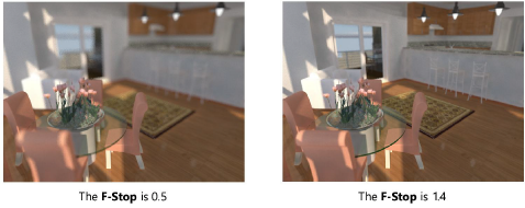
F-Stop |
Select a value, or select Custom F-Stop. F-stop determines how blurry out of focus objects are relative to the focus distance. The larger the F-stop number, the deeper the depth of field, and as a result the less blurry objects appear.
|
|
Custom (f/#) |
If F-Stop is set to Custom F-Stop, enter a custom value equal to or greater than 0.01 |
|
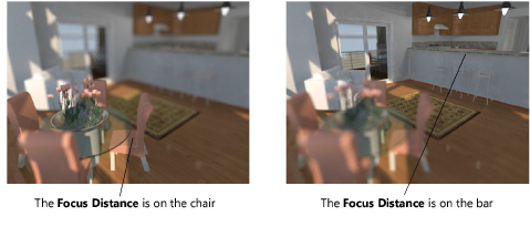
Focus Distance |
Specify the focus distance numerically or click Click to Set Focus Distance to define the focus distance based on objects in the drawing. Focus distance is the point at which objects appear sharpest in front of the camera.
|
|
Click to Set Focus Distance
|
Click to define the focus distance based on objects in the drawing; the cursor changes to indicate the operation is active. Click in the drawing to set the distance. |
|
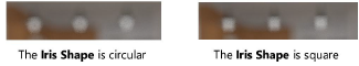
Iris Shape |
Select the iris shape. Bright objects that are out of focus and far from the lens appear blurred and take the shape of the iris diaphragm.
|
|
Exposure |
Uses the exposure options. Exposure is the amount of light that reaches the film or sensor. |
|
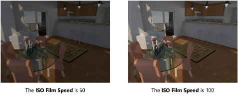
ISO Film Speed |
Select an ISO film speed. ISO is the sensitivity of the film or sensor to light. Higher values create brighter results.
|
|
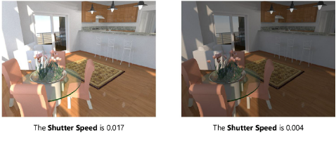
Shutter Speed |
Select the shutter speed, or select Custom Shutter Speed. Shutter speed specifies the amount of time the shutter is open. The shorter the shutter time, the less light reaches the sensor or film.
|
|
Custom Speed (s) |
If Shutter Speed is set to Custom Shutter Speed, enter a custom value |
|
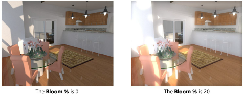
Bloom (%) |
Enter a bloom percentage; values greater than 100% are accepted. The bloom effect adds a glowing halo around the brightest areas of the image, increasing the sense that the light sources are bright.
|
|
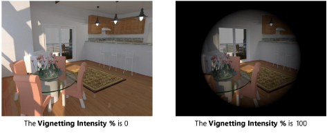
Vignetting Intensity (%) |
Enter a vignetting intensity percentage; values greater than 100% are accepted. Vignetting creates a circular darkening of the image to its edge.
|
|
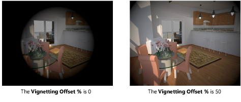
Vignetting Offset (%) |
Enter a vignetting offset percentage
|
|
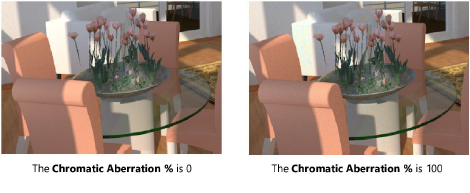
Chromatic Aberration (%) |
Enter a chromatic aberration percentage; values greater than 100% are accepted. Chromatic aberration is the effect of different light colors being refracted by the lens at different angles. It takes place mostly in blurred regions.
|