 Cable numbering rules
Every cable numbering system consists of a set of rules listed in the Edit Numbering System dialog box; when designing a numbering system, place the most specific rules first, and then the more general rules.
The cable numbering rules can seem complex at first; studying the existing rules is helpful when trying to understand how the rules are created and applied.
Each rule consists of two parts: matching criteria plus a cable number format that is applied when the criteria match. The rules are applied, in order, until one that meets the criteria is found; then, the number format from that rule is applied to the circuits.
Match rule criteria
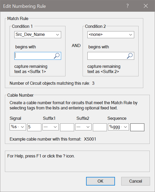
The matching criteria consist of two conditions. Both conditions must be met for the rule to be considered a match, and for the cable number format to be applied to the circuits.
Each condition allows the selection of a parameter (including combinations of source, destination, socket, device, name, and more options selected from the list) and a prefix value or text that you enter. The ? is a wildcard character for the prefix. For example, a Parameter of Src_Dev_Name and Prefix of ?DA searches for source device names that begin with any character plus DA, so the search will find source devices labeled ADA and VDA.
Cable number format
Once both conditions of the matching criteria have been met, the numbering format is applied to the circuits. The numbering format consists of letters and numbers plus tags that extract data from the matching criteria, either Condition 1 or 2. Any text that is not part of a tag is inserted into the cable number as is.
For example, for a matching condition 1 (Src_Dev_Name of ?JF_) that results in VJF_A and a matching condition 2 (Src_Skt_Name of PORT) that results in PORT02, a rule of %s#1#2 results in a cable number of V0102.
You can escape the special characters, ?, #, $, %, ^, &, =, *, /, +, - in the format of the rule by using "\" in front of the operator.
The tag help list shows which characters to use to extract the data and convert it to text or a number.
% inserts the suffix as text (the suffix from either the first or second Match rule)
# inserts the suffix as a number (the suffix from either the first or second Match rule)
$ inserts a number to match either the first or second Match rule wildcard as a number
? is a wildcard, inserting string 1 or 2 as text
%s indicates that the signal type letter is inserted as text
%g is a unique number generator
%u is an incremental generator
Editing as text
The Edit as text option displays the entire currently selected numbering rule as a formula that contains both the matching criteria and the numbering format. The editor allows you to create “normal” rules like the ones created by the Edit Numbering Rule dialog box, or custom rules using any circuit parameters and more than two match conditions.
In the formula, the following characters apply:
^ means “begin with”
& means a logical “AND”
= means IF matches succeed, THEN generate the circuit numbering using this format
For the example above, the text version of the formula is this: Src_Dev_Name^?JF_&Src_Skt_Name^PORT=%s#1#2
Each match rule is defined as a parameter value that begins with (^) a matched string (either ?JF or PORT)
& indicates that both match rules must match for the criteria to be met
= means that if the matches succeed, generate the circuit numbering using the %s#1#2 rule, creating a V0102 number
