 Placing equipment
|
Tool |
Tool set |
|
Equipment Item
|
Layout |
Equipment items can be placed stand-alone or within a rack, and they can be used to identify objects as equipment. Equipment items are typically associated with devices on the schematic layer.
To identify non-rack equipment with a room location, draw a polygonal layout room on the architectural layer with the Layout Room tool.
Rack equipment: If placed in a rack, equipment becomes associated with the rack, inheriting its ID/location and moving with the rack. Modular equipment can optionally be placed within a rack frame located in the rack. To connect rack-mounted equipment to a cable path network, connect the rack.
Equipment items that are placed in 2D racks cannot be connected to drop points.
Stand-alone equipment: Place equipment items in the model and connect them to the cable network; see Creating cable networks.
Associated equipment items and objects: You can associate equipment items with Vectorworks Spotlight objects such as cameras, speakers, lighting devices, and video screens. Valid objects are available for placement from the Event Design tool set.
Associated third-party plug-in objects: You can associate equipment items with third-party plug-in objects. Vectorworks enables third-party developers to access and update equipment items attached to their plug-ins.
Associated devices and equipment items: If the name of the equipment matches that of an existing device, and Link device name is selected, the equipment automatically uses the device’s make and model number. Once the device and the equipment item are associated, the equipment parameters define the device's make and model, as well as its physical and location data.
If the drawing already contains devices, the Create Equipment command automatically creates an equipment item for each device; see Creating equipment items automatically.
To place equipment:
Do one of the following:
Click the tool.
Open the Resource Manager, open the folder containing the equipment items saved with the file or in the user folder, and then double-click an equipment item. The tool is activated. If you click Preferences mode, the dialog box displays the physical dimensions of the equipment item, and Use symbol is selected.
Click to place the equipment in the drawing, within an equipment rack, or over a valid object. The first time you use the tool in a file, a properties dialog box opens. Set the default parameters. The parameters can be edited later from the Object Info palette.
Click to show/hide the parameters.Click to show/hide the parameters.
|
Parameter |
Description |
|
General |
|
|
Name |
Enter the equipment name for labels and reports; if the name is the same as an existing device on the Schematic layer, the device’s make and model information is automatically linked and entered. If attaching the equipment item to an object, name it after the corresponding device. Connect CAD can then recognize the corresponding device on the schematic. Name the equipment item with a CTP_ prefix to create a connector panel. If needed, select Text > Size to change the size of the Name text only. |
|
Link device name |
Associates the equipment item name with all devices that have the same name. Changing the equipment item name also changes the name of the associated devices. When this option is deselected, changing the equipment's name has no effect on the devices, and they become disassociated. |
|
Manufacturer |
|
|
Make/Model |
Enter the manufacturer’s make and model information |
|
Physical |
|
|
Height/Width/Depth |
Enter the dimensions of the equipment |
|
Power (W) |
Enter the power requirements of the equipment in watts |
|
Auto BTU calculation |
Automatically converts the power requirements of the equipment from watts to BTU units (BTU = power in watts x 3.41) |
|
BTU |
To enter power requirements manually, deselect Auto BTU calculation and enter the power requirements of the equipment in BTU units |
|
Weight (kg) |
Enter the equipment’s weight in kilograms |
|
Height RU |
Select the height of the equipment in rack units |
|
Rack Width |
Select whether the width of the item is constrained by the half or the full width of the equipment rack. Select non-rack to use any width, unconstrained by the rack or not placed within a rack. A control point on the item allows you to manually adjust the height and width by dragging. If the Rack Width is constrained, only the height can be adjusted by the control point.
|
|
Mounting |
Select whether the equipment mounts to the front or rear of the equipment rack |
|
Mounting Depth |
Offsets the equipment from the rack by the specified distance |
|
Configuration |
|
|
Modular |
Indicates the equipment is modular, taking up several slots in the equipment rack |
|
Number of Slots |
Enter the number of slots occupied by a modular configuration |
|
Display |
|
|
Show text |
Toggles text display on the equipment item in both 2D and 3D |
|
Text Align |
Select the text alignment for the Name label |
|
Draw in front view |
When the equipment is not placed in a rack, and is not part of a custom panel, draws the equipment in Front view |
|
Use symbol |
Select the option, and then click to select an equipment item resource from the Resource Selector |
|
Location |
Displays the containing layout room and equipment rack ID, as well as the rack location (in rack units) and slot if placed in a rack frame. If only the rack ID is specified, the equipment is placed below the rack. If the equipment item is associated with a device on the Schematic layer, the location information updates automatically for the device. |
|
Custom Panel |
Name the equipment item with a CTP_ prefix to enable these additional connector panel parameters. See Creating connector panel layouts. |
|
Get Connectors |
Places detailed views of associated connectors on the custom connector panel equipment |
|
Create Panel Devices |
Places corresponding Conn panel devices on the Rack Elevation layer |
|
Edit Schematic Device(s) |
Select to edit an associated device on a schematic layer. The option navigates to associated devices, which are automatically selected for editing. See Editing devices associated with equipment. This option is enabled only when the equipment item has at least one associated device. |
An equipment item object includes a control point, which is visible in 3D views. If you are creating a cable network, drag the control point to a drop point object to connect it; valid drop points are highlighted. Drag the control point off of the drop point to disconnect it (or select Detach from Drop Points from the object drop-down context menu).
You can connect multiple equipment items to a drop point by selecting all of the equipment control points with the Unrestricted Interactive Scaling mode of the Selection tool enabled. Drag the control points towards the drop point.
An equipment item can also be associated with a drawing object from the Event Design tool set. When placing the equipment item, place it on the valid object. Valid objects are highlighted at placement; after placement, the equipment item is identified as an icon (in Top/Plan view) or a locus (in 3D views) over the object.
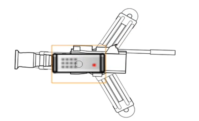
Alternatively, after placement, drag the equipment item's control point to the object to attach it. Once the equipment item and the object are associated, they move together. Next, attach the equipment item to a cable path network or to a drop point. You can also use the Cable tool from the Cable Route tool set to make this connection.
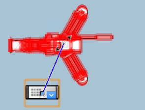
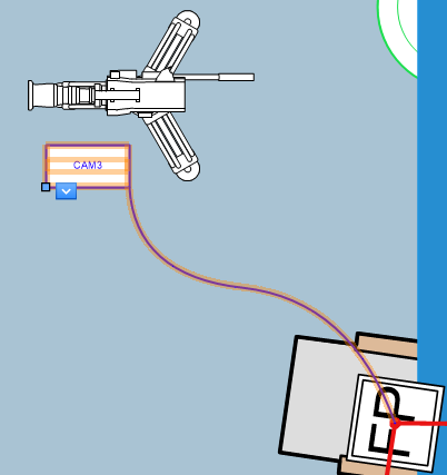
Attaching an equipment item to a camera, and attaching the equipment item to a drop point
Detach the equipment item from the object or drop point using the drop-down context menu. Select the Detach From [object] or Detach from Drop Points command.
