Re-routing circuits
|
Mode |
Tool |
Tool set |
|
No Breakout Nodes
Display Breakout Nodes
|
ReRoute Circuits
|
Schematics |


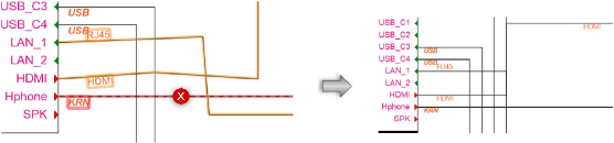
Multiple circuits can be re-routed to align them graphically to, and if needed, combine the routing with, a selected circuit. The circuits do not need to be of the same signal type.
This can clean up a drawing by making circuits parallel, for example, or by making them follow a particular circuit’s route. You can also convert a set of circuits into a certain circuit type (such as rounded polyline circuits), create fan-out circuits, and eliminate extra circuit routes.
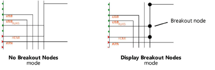
When circuit routes are combined as part of the re-routing, they can display with or without breakout nodes, which indicate where the circuits split off from the bus to their connected sockets.
To re-route circuits:
Select the circuits to be re-routed.
Click the tool and click either No Breakout Nodes mode or Display Breakout Nodes mode. As you move the cursor over the circuits, the highlighted circuit is the one that the selected circuits will align to.
Click to align and re-route the circuits.
Click and drag the highlighted reference circuit to space out bussed circuits.