Inserting fastener objects using the Fastener tool
|
Tool |
Tool set |
|
Fastener
|
Fasteners |

Several types of fastener objects can be inserted by clicking the Fastener tool and specifying object parameters from the Tool bar.

|
Mode |
Description |
|
Screw or Screw/Washer/Nut Combination
|
Inserts a screw and nut object which can be composed of a variety of screw, washer, and/or nut components; hex bolts, square bolts, hex screws, cap screws, and machine screws can all be inserted using this tool mode |
|
Nut
|
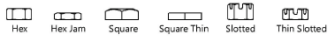
Inserts a nut object, including hex, hex jam, slotted hex, and square nuts |
|
Plain Washer
|
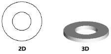
Inserts a plain washer object |
|
Lock Washer
|
Inserts a lock washer object |
|
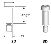
Shoulder Screw
|
Inserts a shoulder screw object |
|
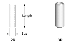
Set Screw
|
Inserts a set screw object |
|
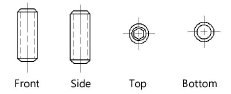
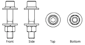
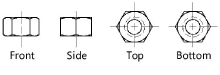
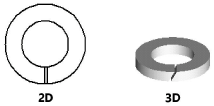
2D Front View
|
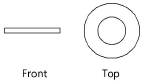
Inserts the selected item as a 2D object in front view |
|
2D Side View
|
Inserts the selected item as a 2D object in side view |
|
2D Top View
|
Inserts the selected item as a 2D object in top view |
|
2D Bottom View
|
Inserts the selected item as a 2D object in bottom view |
|
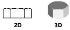
3D Object
|
Inserts the selected item as a 3D object |
|
ASME Inch
|
Inserts the selected object using ASME inch standards |
|
ASME Metric
|
Inserts the selected object using ASME metric standards |
|
ISO
|
Inserts the selected object using ISO standards |
|
DIN
|
Inserts the selected object using DIN standards |
|
Preferences
|
Opens the Preferences dialog box for specification of additional object parameters |


To insert a fastener object:
Click the tool and click the desired fastener object.
Click the Tool bar button to insert either a 2D object in a specific view or a 3D object.
For objects that do not have bottom view (because it is the same as the top view), the top view is drawn when either the 2D Top View or 2D Bottom View mode is clicked. The same applies to the front and side view.
Click the Tool bar button to insert the object using ASME (inch or metric), ISO, or DIN standards.
Click Preferences to specify additional object parameters before placing the object in the drawing. Parameters vary based on the object selected for insertion, and show the available variations for a specified object size. Additional parameters display in the Object Info palette. Refer to the following table for detailed object parameter information.
If inserting a linear object (such as a bolt, screw, or screw and nut object), click in the drawing area to set the start point, drag to set the object’s length, and click again to set the object’s end point. For all other objects (such as washers and nuts), click in the drawing area to place the selected point object.
Parameters can be edited later from the Object Info palette.
Screw or Screw/Washer/Nut Combination parameters
Click to show/hide the parameters.Click to show/hide the parameters.
|
Parameter |
Description |
|
Screw or Screw/Washer/Nut Combination |
|
|
View |
Select the 2D view
|
|
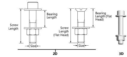
Size |
Select the screw size (ASME inch), or the diameter/thread pitch (ASME metric, DIN, and ISO) |
|
Configuration |
Opens the Configuration dialog box to select size, screw/bolt, washer, and nut type. See the following pages for illustrations of the available lock washers, washers, and nuts. The list of screw/bolt, washer, and nut types varies depending on the selected size. Not all types are available for all sizes. |
|
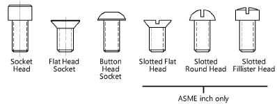
Screw/Bolt Type |
Specify the screw/bolt type |
|
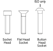
Cap screw ASME inch and metric |
|
|
Cap screw DIN and ISO |
|
|
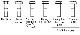
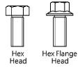
Hex bolt/screw ASME inch and metric |
|
|
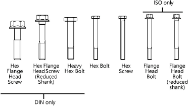
Hex bolt/screw DIN and ISO |
|
|
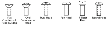
Machine screw ASME inch |
|
|
Machine screw ASME metric |
|
|
Machine screw DIN and ISO |
|
|
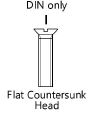
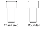
Head Style (ASME metric, ISO, and DIN only) |
For cap screws (ASME metric, ISO, and DIN), specify the head style
|
|
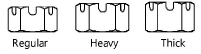
Top/Bottom Lock Washer |
Draws a top and/or bottom lock washer; several lock washer types are available |
|
Top/Bottom Washer |
Draws a top and/or bottom washer; several washer types are available |
|
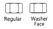
Nut |
Draws a nut. For Hex, Style 1 and Hex, Style 2 nut ISO types, specify either a regular or washer-face Nut Form; several nut types are available |
|
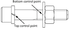
Bearing Length |
Specify the bearing length or click and drag the bottom bearing length control point to define the bearing length graphically
|
|
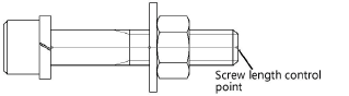
Screw Length |
For a custom length value, deselect Use Standard Length Increments and enter the length under the screw head; alternatively, click and drag the screw length control point to define the length graphically . |
|
Thread Pitch (ASME inch only) |
For ASME inch sizes, specify Unified National Coarse or Unified National Fine threads |
|
Thread Style |
Select the 2D thread style; see Fastener object thread styles |
|
Use Standard Length Increments |
Automatically adjusts the length to the nearest increment based on size, per ASME, ISO, or DIN standards; deselect to enter a custom length |
|
Adjust Screw Length Automatically |
Automatically adjusts the screw length to keep the screw threads within a nut or to prevent the bearing length from exceeding the screw length |
|
Show Threads |
Displays the 3D screw/bolt with threads
|
|
Draw Underhead Fillet |
Draws a fillet under the head of the 2D hex bolt/hex screw |
|
Show Center Line |
Draws the 2D screw and nut with center line(s) |
Nut parameters
Click to show/hide the parameters.Click to show/hide the parameters.
|
Parameter |
Description |
|
Nut |
|
|
Size |
Select the nut size |
|
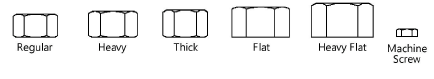
Type |
Specify the nut type |
|
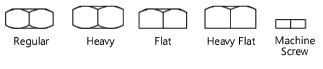
ASME inch |
Hex nuts
|
|
Hex jam nuts
|
|
|
Slotted hex nuts
|
|
|
Square nuts
|
|
|
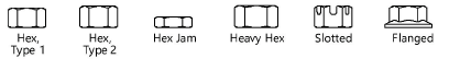
ASME metric |
|
|
ISO |
|
|
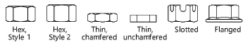
Form |
For Hex, Style 1 and Hex, Style 2 nut (ISO) objects, specify either a regular or washer-face form
|
|
DIN |
|
|
View |
Select the 2D view
|
|
Show Center Line |
Draws the 2D nut with center line(s) |
|
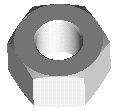
Show Hole |
Draws the 3D nut with a center hole
|
|
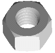
Show Threads |
Draws the 3D nut with threads
|
Washer parameters
Click to show/hide the parameters.Click to show/hide the parameters.
|
Parameter |
Description |
|
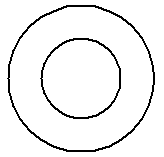
Plain Washer |
|
|
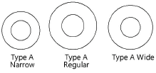
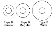
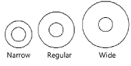
Type/Series |
Specify the plain washer type |
|
ASME inch |
|
|
|
|
|
ASME metric |
|
|
ISO |
|
|
DIN |
Type is not applicable for DIN objects
|
|
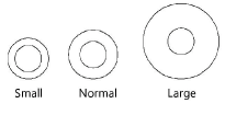
Size |
Select the plain washer size |
|
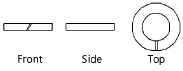
View |
Select the 2D view
|
|
Show Center Line |
Draws the 2D plain washer with center line(s) |
|
Lock Washer |
|
|
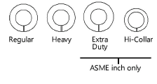
Series (ASME inch and metric and ISO only) |
Specify the lock washer series (not applicable for DIN objects)
|
|
Size |
Select the lock washer size |
|
View |
Select the 2D view
|
|
Show Center Line |
Draws the 2D lock washer with center line(s) |
Screw parameters
Click to show/hide the parameters.Click to show/hide the parameters.
|
Parameter |
Description |
|
Shoulder Screw |
|
|
Size |
Select the shoulder screw size |
|
Length |
For a custom length value, deselect Use Standard Length Increments and enter the length under the screw head |
|
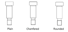
Head Style (ISO only) |
Select the head style
|
|
Thread Style |
Select the 2D thread style; see Fastener object thread styles
|
|
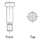
View |
Select the 2D view
|
|
Draw Underhead Fillet (ASME inch, ASME metric, and DIN only) |
Draws a fillet under the head of the shoulder screw |
|
Use Standard Length Increments |
Automatically adjusts the length to the nearest increment based on size, per ASME, ISO, or DIN standards; deselect to enter a custom length |
|
Show Center Line |
Draws the 2D shoulder screw with center line(s) |
|
Show Threads |
Draws the 3D shoulder screw with threads
|
|
Set Screw |
|
|
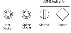
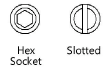
Head Type |
Specify the set screw head type |
|
ASME inch and metric |
|
|
DIN and ISO |
|
|
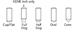
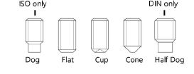
Point Type |
Specify the set screw point type |
|
ASME inch and metric |
|
|
DIN and ISO |
|
|
Size |
Select the set screw size |
|
Length |
For a custom length value, deselect Use Standard Length Increments and enter the length under the screw head |
|
Thread Pitch (ASME inch only) |
For ASME inch sizes, specify Unified National Coarse or Unified National Fine threads |
|
Thread Style |
Select the 2D thread style; see Fastener object thread styles |
|
View |
Select the 2D view
|
|
Use Standard Length Increments |
Automatically adjusts the length to the nearest increment based on size, per ASME, ISO, or DIN standards; deselect to enter a custom length |
|
Show Center Line |
Draws the 2D set screw with center line(s) |
|
Show Threads |
Draws the 3D set screw with threads
|