Placing lighting pipe objects
|
Tool |
Tool set |
|
Lighting Pipe
|
Rigging |
Insert and configure a lighting pipe object with the Lighting Pipe tool. Lighting pipe objects function as rigging objects, so lighting devices and other loads can attach directly to the lighting pipe. Lighting pipes support full 3D rotation, and they can be used to create schematic views.
In addition to individual objects created using the Lighting Pipe tool, it you can access a variety of standard lighting pipe resources and custom styles (see Concept: Plug-in object styles).
![]()
![]()
Secondary modes - Point Insertion mode
![]()
Secondary modes - Line Insertion mode
|
Mode |
Description |
|
Point Insertion
|
Inserts the pipe with two clicks, to place and set the rotation |
|
Line Insertion
|
Inserts the pipe as a line to define the length |
|
Polyline Insertion
|
Inserts the pipe using the polyline creation options |
|
Length |
For Point Insertion mode, sets the length of the pipe |
|
Align Left (Point Insertion mode only)
|
Inserts the pipe with a left-aligned insertion point |
|
Align Center (Point Insertion mode only)
|
Inserts the pipe with a center insertion point |
|
Align Right (Point Insertion mode only)
|
Inserts the pipe with a right-aligned insertion point |
|
Vertical (Point Insertion mode only)
|
Inserts a vertical pipe |
|
Vertex (Line Insertion mode only)
|
Inserts a pipe from its start point to its end point |
|
Center (Line Insertion mode only)
|
Inserts a line from its center point |
|
Polyline creation options (Polyline Insertion mode only) |
For Polyline Insertion mode, selects the method for drawing the polyline upon which the object is based; see Creating polylines. |
|
Preferences
|
Opens the object properties dialog box to set the default preferences for lighting pipes |
|
Style |
Opens the Resource Selector to select a symbol for placement; double-click a resource to activate it |

To insert a lighting pipe object:
Click the tool.
Do one of the following:
Click Style on the Tool bar to select a resource from the Resource Selector.
Click Preferences to open the object properties dialog box and specify the tool’s default parameters.
The parameters can be edited later from the Object Info palette.
Do one of the following:
Click Point Insertion mode and the needed insertion point alignment submode. Set the pipe Length.
Click Line Insertion mode and either click Vertex submode to place the pipe from start to end points, or Center submode to place it from the center to an end.
Click Polyline Insertion mode and use the polyline creation modes to insert the pipe.
Alternatively, create a polyline and then select the Create Objects from Shapes command (see Creating objects from shapes).
Click in the drawing area to draw the lighting pipe according to the modes selected.
Optionally, create a style resource from the object (see Creating plug-in object styles).
Click to show/hide the parameters.Click to show/hide the parameters.
|
Parameter |
Description |
|
Roll Angle |
Rotates the lighting pipe on its X axis; the pipe rotates around its insertion point |
|
Hanging Angle |
Rotates the lighting pipe on its Y axis; the pipe rotates around its insertion point. When this angle is adjusted, attached load objects may appear to overlap in Top/Plan view. |
|
Rotation |
Rotates the lighting pipe on its Z axis; the pipe rotates around its insertion point |
|
Style |
Replace, remove, or edit the current style, or create a new plug-in object style for this object. Editing a style changes all instances in the file that use the style. |
|
Hide Style Parameters |
Hides the parameters that are set by style; these cannot be edited from the dialog box or Object Info palette |
|
General |
|
|
Shape |
|
|
Insertion Point |
Select the insertion point of the object, without moving the object |
|
Total Pipe Length |
Specifies the total length of the lighting pipe; for a single-segment lighting pipe, the length can be edited by changing this value. (Change the segment length or edit multi-segment pipes with the Reshape tool.) |
|
Show Direction |
Places a directional indicator on the lighting pipe |
|
Arc Radius |
For single-segment curved pipes, specifies the radius of the arc |
|
Data |
|
|
Position Name |
Enter a name for identification and reporting purposes. When the lighting pipe is used as a hanging position, this name automatically populates the Position field of any attached load objects. |
|
Index |
Specifies a unique identifier for the object, which is combined with the Position Name for identification and reporting |
|
Location |
Optionally, specifies the location for use in reports |
|
Pipe |
|
|
Draw Pipe |
Shows or hides the 2D component of the lighting pipe |
|
Line Type |
Select either a single or double line for Top/Plan views |
|
Diameter |
Sets the pipe diameter for all views |
|
Render Profile |
Select the 3D profile of the pipe; this setting affects rendering speed (shapes other than round may render more quickly) |
|
Construction Material |
Select the material (aluminum, steel, and so on) of the pipe |
|
Wall Thickness |
Specifies the thickness of the pipe wall |
|
Total Weight |
Displays the total weight of the lighting pipe based on its Total Pipe Length and Construction Material |
|
Smooth Corners |
Draws a pipe with rounded rather than mitered corners |
|
End Marker |
Specifies whether to display the end(s) of the pipe with an end marker in Top/Plan view |
|
Show Centerline Snap Guide |
Displays a centerline in 3D view; in Top/Plan view, the centerline displays when the Line Type is set to Double |
|
Tick Mark |
|
|
Display ticks as |
Choose how to display evenly-spaced marks to assist with lighting device placement; all options except None also provide master snap points along the lighting pipe when hovering over it. |
|
Centers |
Specifies the distance between tick mark centers |
|
Snap intervals between ticks |
Specifies the distance between master snap points |
|
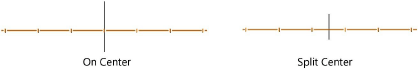
Centered on |
Spaces the tick marks based on the total length of the pipe, or based on each segment of a pipe that is considered divided into two equal sections |
|
Origin |
Starts the tick mark placement at the center of the pipe or split equally from the center of the pipe
|
|
Type |
Select Line or Dot as the 2D tick mark indicator |
|
Size |
Specifies the length of line tick marks or the diameter of dot tick marks |
|
Gap Length |
Adds a gap on either side of the tick mark; specify the gap length |
|
Offset |
Specify a positive or negative value to shift the tick marks right or left from their centers |
|
Align Tick Marks to Grid |
Aligns the center tick mark with the snap grid (see Snapping to the grid); this does not change the tick mark spacing but it may change the Offset value |
|
Classes |
|
|
Use Standard Classes |
Opens the Use Standard Classes dialog box to set the class prefix used by the pop-up class settings below. Select Existing class to use an existing class from the document as a prefix. Select Other prefix to create a new custom prefix without creating the class. |
|
List of lighting pipe parts |
To control appearance and visibility, select a class from the list of classes present in the drawing, or create a new class. Select <Lighting Pipe Class> to place the part attributes in the same class as the lighting pipe object. |
|
Opens the Lighting Pipe Settings dialog box, to set the default class for the lighting pipe. Select the Make default for new documents option to always use the specified class as the default class for lighting pipe objects in new files. |
|
|
Select Truss System |
Selects the current lighting pipe and any other connected structural elements in the system |
|
Vertex Parameters |
Edits the pipe vertices; see Editing vertex-based objects |