Marionette tutorial: Creating a simple cabinet
This more advanced tutorial demonstrates how to create a simple open-faced cabinet composed of three rectangular prisms, one each for the top, body, and cavity.
Step 1: Create a network that defines a rectangular prism
Create a rectangular prism (an extruded rectangle) to serve as the body of the cabinet. For now, the body is a solid object; later steps in the process will create a top for the cabinet and a cavity in the body.
To create a network that defines the rectangular prism:
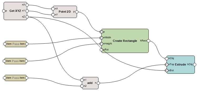
Insert the following nodes to create a network as illustrated.
Use the Search functionality in the Resource Selector to help you find the nodes you need.
Create Rectangle node: This serves as the shape on which the cabinet is based; its dimensions are defined by other nodes. The rectangle is wired to the Extrude node to define the profile to be extruded.
Extrude node: With inputs from all the other nodes, this serves as the 3D base shape for the cabinet.
Get XYZ node: This node reads the values provided by a Point 3D or 3D Vector node, and separates the values into the X, Y, and Z components.
Point 2D node: The X and Y values are used to create a 2D point that defines the location of one corner of the rectangle.
Three Pass nodes: These are wired to the Width and Height ports of the Create Rectangle node and to the Add node. Pass nodes simply send what goes into the node back out of the node. In this example, Pass nodes are only for organizational purposes.
Add node: This adds the Pass node output to the Z value from the Get XYZ node to determine the top of the extrude.
Connect the wires as illustrated.