 Wall closure settings
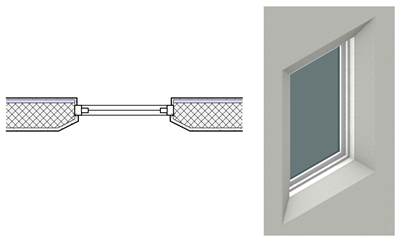
You can define the wall closure profiles and component wrapping conditions at wall openings for inserts such as doors and windows. Not only can the exterior and interior sides of the walls have different profile settings, but all four edges that border the opening can be defined individually. Each component can have individual wrapping settings.
Wall closure settings can be created for wall styles, for wall instances, and/or for insertion object instances, such as windows and doors in the wall. The closure settings for a wall instance can override the wall style's closure settings, and the closure settings for an inserted object can override the settings of the wall it is in. This allows you to use style settings and symbol definitions for consistency throughout a file, but to customize specific walls as needed.
Plug-in objects and symbols that can be inserted into walls, such as windows and doors, have additional wall insertion options that can affect the wall closure. Use wall closure must be selected for the inserted object for some features to work (see Additional plug-in object style and instance options and Creating symbol definitions).
The profiles and component wrapping are visible in both Top/Plan and 3D views.
To define wall closure profiles and component wrapping settings, do one of the following:
To define the settings for wall instances before insertion, click Wall Closure at Inserts on the Definition tab of the Wall Preferences dialog box.
To define the settings for selected walls, click Wall Closure at Inserts on the Object Info palette.
To define the settings for a wall style, click Wall Closure at Inserts on the Edit Wall Style dialog box.
To define the settings for a selected object inserted in the wall, such as a window or a door that supports wall closures, click Wall Closure on the Object Info palette.
These settings can be set simultaneously for multiple selected walls of the same wall style, or multiple selected inserts in walls of the same wall style.
To apply the settings for a selected insertion object to the parent wall (changing the wall's settings), right-click on the insert and select Apply Closure Settings to Wall from the context menu. The wall's settings in the Wall Closure at Inserts dialog box are changed to those of the insert. Use wall settings is automatically selected in the insert's Wall Closure dialog box. All other inserts in the wall that have Use wall settings selected update automatically to use the new settings.
The Wall Closure at Inserts dialog box (for a wall object) or the Wall Closure dialog box (for an inserted object) opens.
Click to show/hide the parameters.Click to show/hide the parameters.
|
Parameter |
Description |
|
Use wall style settings (Available for a wall instance) |
For each tab, select to use the wall style's closure profile and/or wrapping settings; deselect to override the style settings for the selected wall |
|
Use wall settings (Available for an insert object) |
For each tab, select to use the wall's closure profile and/or wrapping settings; deselect to override the wall settings for the selected insert object |
|
Edit Edge (Profile Shapes and Wrappings tabs) |
For each tab, select an edge of the opening to define the profile and/or wrapping settings. |
|
Preview |
Dynamically previews the current settings. When Edit Edge is set to Left or Right, a Top/Plan preview of the wall structure displays as if the wall is drawn from left to right, with the exterior at the top. When Edit Edge is set to Top or Bottom, a vertical section displays with the top edge of the opening at the top. When this dialog box is opened for wall settings, a generic insert displays to represent a door or window insert. When the dialog box is opened for an insert, such as a door or window, the insert displays. |
|
Insert Depth |
Enter the insertion object's thickness, so the preview more accurately simulates the real object; this dimension only affects the preview and does not change the object's settings |
|
Insert Origin |
Select the object's insertion point, which is indicated by a locus; this selection only affects the preview and does not change the object's settings |
|
Profile Shapes tab |
|
|
Use Settings from Edge |
Settings for each edge can be independent of the others or can take on the settings from another edge. To use the profile settings from a different edge, select the edge; "(Use [edge])" displays by the edge name, and the shape type controls become unavailable. |
|
Exterior/Interior Shape Type |
Select the exterior and interior shape types; for Splay and Round types, enter the relevant dimensions.
In this example, the Exterior Shape Type is Splay and the Interior Shape Type is Round; the right edge has Use Settings from Edge set to Left A round profile type cannot use custom component thicknesses on the Wrappings tab. |
|
Profile Offsets tab |
|
|
Calculation setting |
Click the icon in the Gap, Overlap, or Offset column to indicate how to calculate the profile: Gap: Calculate the gap by subtracting the overlap from the offset; the gap defines the distance between the insert's jamb, frame, or other closure object and the the rough opening in the wall. Overlap: Calculate the overlap by subtracting the gap from the offset; the overlap defines how much the profile overlaps the jamb, frame, or other closure object. Offset: Calculate the offset by adding the gap to the overlap. Fields in the Gap, Overlap, and Offset columns below are enabled or disabled depending on selection. |
|
Edge settings |
Edge settings fields are enabled or disabled depending on the interplay of calculation setting, wall (style) setting, and Use Settings from selections that determine which fields are currently editable. Set the offset dimensions for the closure's exterior and interior edges. If Use Settings from for any edge is set to a different edge, the field is set to match the selected edge and is disabled. The profile gap, overlap, or offset is calculated according to the calculation setting above, using the dimensions entered. To wrap selected wall components into the opening on all edges without having to measure or calculate an offset, see the Wrap into Opening option on the Wrappings tab. |
|
Fixed Value when Insert Provides Gap |
If the inserted object defines the gap dimensions, select whether the insert's overlap or offset value is fixed for calculations |
|
Wrappings tab |
|
|
Use Settings from Edge |
To use the wrapping settings from a different edge, select the edge |
|
List of components |
A list browser lists the components that form the structure of the wall, in order from top to bottom; the core component is indicated but can't be changed from this list. Set the Insert Loc. and Offset columns as described for the Definition tab in Standard wall preferences. To enable the wrap options for a component, click to place a check mark in the Wrap column for that component. Components located towards the exterior of the wall from the core component wrap toward the interior face of the wall, and components located towards the interior from the core component wrap toward the exterior face. If the wrapping settings create a conflict between components, the component nearest the wall exterior has priority. Wrap To: If the component should wrap to another wall component, click in the column and select the wrap-to location from the list. Offset: When the component is set to wrap, optionally enter a positive or negative value to offset the end of the wrap from its location. Wrap to Insert: If the component should wrap to the edge of the insert rather than to a wall component, click to place a check mark in the column. Use Custom Thickness: To use a custom thickness for the wrapped portion of the component, click to place a check mark in the column. Custom Thickness: Enter the custom thickness value Wrap into Opening: To project a component into the opening by the component's thickness, click to place a check mark in the column. Only one component on each side of the core can be set to wrap into the opening at a time, but all components more distant from the core than the wrapping component also wrap into the opening. Repeat for other components as needed. Round interior/exterior profile types, assigned on the Profile Shapes tab, cannot use a custom component thickness. |
|
Clear All Wrapping |
Removes all the wrapping settings in the list browser |
The profile and wrapping settings can be combined in a variety of ways, as needed for each specific wall and insert. Component colors in the following examples are for illustrative purposes.
The Exterior Shape Type is Splay and the Interior Shape Type is Round. There are no profile offset or wrapping settings.
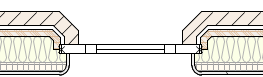
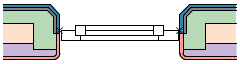
The blue, gray, and green components on the wall exterior, and the red component on the interior face are all set to Wrap to Insert. The gray exterior component is also set to Wrap into Opening; the blue component farther from the core must also wrap into the opening, along with the gray.
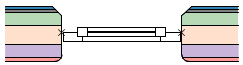
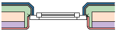
The blue and gray components on the wall exterior, and the red component on the interior face are all set to Wrap to Insert. The green component wraps to the purple component, with an offset, and uses a custom thickness. No components are set to wrap into the opening.
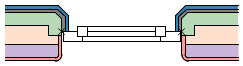
The blue and gray components on the wall exterior, and the red component on the interior face are all set to Wrap to Insert. The green component wraps to the red component, without an offset or a custom thickness. No wall components are set to wrap into the opening. The window insert object has a profile offset on the exterior in the Profile Offsets tab, which overrides the wall settings.
