Customizing ConnectCAD objects
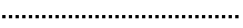
ConnectCAD circuits, devices, sockets, adapters, equipment items, and other objects can be customized. This is useful when you need to suit client or venue needs with a specific look, or to create an identifiable design presence in your drawings.
If opening another user's file with custom signals, connectors, or cable types, the custom parameters are available from the Object Info palette, but are not saved in the user folder until you add them with the ConnectCAD Settings dialog box.
Customizing the basic device
The Device tool, in Basic Device mode, inserts a symbol named Basic Device. The Create Devices from Worksheet command and the Device Builder tool can also use this symbol. The symbol definition can be edited from the Resource Manager; see Editing symbol definitions. The symbol definition is located in the ConnectCAD\Device\Devices folder. When editing the symbol definition, you can:
Specify default device name and other parameter information from the Object Info palette.
Add custom graphics to the symbol definition to use them by default when the symbol is placed into the drawing.
Add linked text to the basic device by following the instructions below.
Edit the tag symbol definition while editing the device symbol definition, simply by performing a nested edit while editing the device symbol.
Do not add sockets to the basic device symbol; they will not be inserted with the device.
Displaying custom records
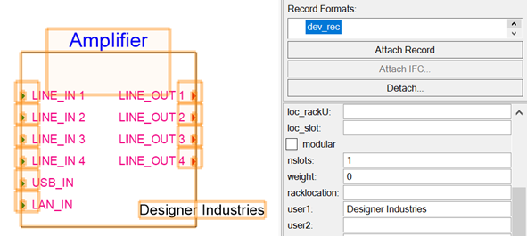
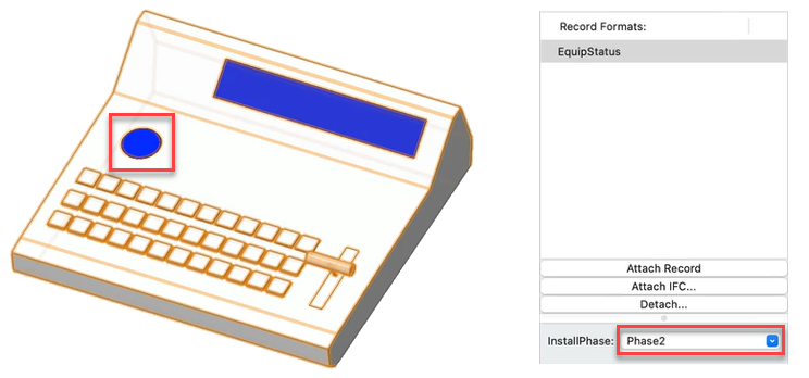
You can display custom information in linked text and linked symbols on device, socket, adapter, and equipment objects. The information can be static text, standard object parameters, and/or custom record data.
Alternatively, the Data Manager can automatically create objects with the information already attached. See Concept: Data mapping and data sheets.
To display custom fields on device, socket, adapter, and equipment objects:
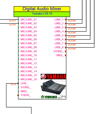
Create a custom record for each type of object you want to customize, as described in Creating record formats. Add the desired record fields for the values that will display with the object, and default values if desired. Typical examples include adding text to display in a text field, or adding popup selections to be displayed.
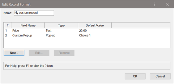
Attach the custom record to the object to customize from the Data tab of the Object Info palette.
Double-click on the object to enter object editing mode; see Object editing mode.
To add linked text:
Create a text field next to or inside the object with the Text tool (see Inserting text) to serve as the placeholder for the information to display. Format the text with the desired font and style.
In the Object Info palette for the selected text (the selection displays as Text in [object]), select the Is linked text option under ConnectCAD Text Link Data.
To add a linked symbol:
Insert a symbol with the Symbol Insertion tool (see The Symbol Insertion tool).
In the Object Info palette for the selected symbol (the selection displays as Symbol in [object]), select the Is linked option under ConnectCAD Linked Data.
If desired, the symbol to display can be mapped to a particular value or range of values. Click Edit Symbol Linkage to specify the symbol to display for each parameter value or parameter range. The Link Symbol dialog box opens.
Parameter types are detected automatically, but you can also choose an option. For discrete parameters (boolean and choice lists) and for custom linkage, the By values choice is selected. For continuous parameters, By ranges is selected.
Click to show/hide the parameters.Click to show/hide the parameters.
|
Parameter |
Description |
|
By values |
Add a symbol for each object parameter value or field of the attached record. Click Add to add a Value/Symbol row, and then click in each column to specify the value and to select the symbol to display. Click Delete to remove the selected row. |
|
By ranges |
Add a symbol for each range of object parameters. Click Add to add a Range/Symbol row, and then click in each column to specify the upper and lower ends of the range, and to select the symbol to display. Click Delete to remove the selected row. Non-numeric values display by text sorting order. |
You can edit the symbol link from the Object Info palette by clicking Edit Symbol Linkage. The Link Symbol dialog box opens.
In the Field list, do one of the following:
Select a single field from the object parameters or the attached record.
Click Custom Linked Text or Custom Formula to enter a custom link formula.
If you're using a custom link formula, select it from the Custom Linked Text list. To create a formula, click Edit Custom Linked Text or Edit Custom Linked Symbol.
Default link formulas cannot be edited.
The Edit Custom Linked Text dialog box opens.
Click to show/hide the parameters.Click to show/hide the parameters.
|
Parameter |
Description |
|
Name |
Provide a name for the custom link formula; the formula can be selected later from the Custom Linked Text list on the Object Info palette |
|
Custom Linked Text Formula |
Displays the current link formula; you can insert multiple fields, and also manually add text or punctuation to the formula |
|
Insert Field |
Inserts a field into the link formula; select a parameter or custom record format field |
|
Delete |
Deletes the currently displayed custom link formula. Default formulas cannot be deleted. |
When the linked text or linked symbol is created, exit the object.
Edit each object instance from the Data tab of the Object Info palette to enter data in the fields as needed.
Custom linked text and linked symbols may depend on an attached record. Formulas are saved in a CustomLinkFormulas.xml file in the user folder. If the formula or record is deleted or detached later, the formula displays instead, or the displayed text may be incomplete.
Save the object as a symbol if desired.
Devices can be saved as a symbol by clicking Save as Symbol from the Object Info palette; for sockets or equipment items, see Creating symbol definitions.
Displaying a field from a custom record
Displaying custom linked text
Displaying a custom linked symbol
Customizing circuit graphics
The appearance of a selected circuit, or the default appearance of all circuits, can be set from the Edit Circuit Graphics dialog box. Arrow circuits are circuits created with the Arrow mode of the Connect tool.
To customize the appearance of circuit graphics:
Do one of the following:
To set the default appearance of all circuits, select ConnectCAD > ConnectCAD Settings. On the General Settings pane, click Edit Default Circuit Graphics.
To set the appearance of an existing circuit, right-click on the circuit and select Edit Circuit Graphics from the context menu.
The Edit Circuit Graphics dialog box opens. Customize the fields to display; edit the appearance of arrow circuits and/or the bubble label of other circuits.
Click to show/hide the parameters.Click to show/hide the parameters.
|
Parameter |
Description |
|
Customize arrow/Customize bubble |
Enables the customization; to use the default, deselect the option |
|
Arrow Text Formula/Bubble Text Formula |
As fields are selected from Insert Field, the formula is created; the results display in the Preview. Add text to the formula if needed. Even if the formula occupies more than one line, the resulting display is always on one line. |
|
Insert Field |
Select the parameter or record value to display in the circuit; the layer option is useful for arrow circuits |
|
Arrow Style/Bubble Style |
Select the arrow or bubble style |
|
Preview |
Displays the results of the selected formula and style |
From the Insert Field list, select a field to display on the circuit arrow or in the bubble. The formula displays in the Arrow Text Formula or Bubble Text Formula, where it can be edited. Build up the formula by selecting items from the Insert Field list. In addition to default Circuit parameters, you can select from custom record formats that are saved in the file; if the custom record is attached to the circuit, its data displays.
The preview shows the appearance of the circuit label.
Customizing options
Advanced users can customize default items such as cable lengths, signal types, and connector types. The selections available come from simple tab-delimited text files located in the Plug-Ins/connectCAD_Data folder within the application folder.
To create custom files for yourself, copy the files to your user folder and edit them: [User]/Plug-ins/connectCAD_Data
To share custom files with coworkers, place them in a workgroup folder: [Workgroup]/Plug-ins/connectCAD_Data
Edit the files to suit company standards or to add more options. The first row is a header that describes the function of each column; additional rows with custom options can easily be added, edited, or deleted using a text editor application.
|
File name |
Purpose |
|
CableLengths.txt |
Standard cable lengths available in Cable Length list of the Object Info palette for circuits |
|
ConnectorTypes.txt |
Connector types |
|
JFdata.txt |
Physical size and label pitch for jackfields |
|
SignalTypes.txt |
Signal types |
|
TPdata.txt |
Physical size and label pitch for terminal panels |