Creating polyline roadways
|
Mode |
Tool |
Tool set |
|
Modes for Creating polylines |
Roadway (Poly)
|
Site Planning |

The Roadway (Poly) tool creates a road defined by a path polyline or polygon. In Top/Plan view, the curbs and pavement are represented by filled polygons. In 3D views, extrudes are generated to represent the curbs and pavement. Polyline roadways can also be created by drawing a polyline or polygon and then selecting the Create Objects from Shapes command (see Creating objects from shapes).
To create a road with the Roadway (Poly) tool:
Click the tool.
Multiple roadway tools share the same position on the tool set. Click and hold the mouse on the visible tool to open the Pop-out tools list and select the desired tool.
Click to begin drawing the roadway polyline path; click to set each polyline vertex. Click again back at the start point (or press K) to complete a closed polyline, or double-click to create an open path polyline. For more information on polylines, see Creating polylines.
The first time you use the tool in a file, a properties dialog box opens. Set the default parameters. The parameters can be edited later from the Object Info palette.
Click to show/hide the parameters.Click to show/hide the parameters.
|
Parameter |
Description |
|
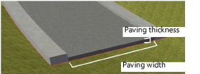
Paving Width/Thickness |
Sets the width and thickness of the roadway paving
|
|
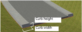
Curb Width/Height |
Sets the width and height of the roadway curb
|
|
Show joints |
Displays the roadway joints (the hidden sides where there is no curb) as dashed lines |
|
Show stations |
Stations report the road elevation at intervals along the roadway. Select the option to show station information along the roadway curves at corner vertices; in Top/Plan view, the display includes the segment index (the number of the station, counted from the start of the roadway polyline) and the station offset from the beginning of the road curve. In 3D views, a locus displays. |
|
Create planar pad for site model |
Creates an embedded planar pad site modifier around the road, following the road curvature and the elevation defined at each station point. A path polyline with many vertices will have less segmentation when the pad is created; increase the number of vertices with the Reshape tool if necessary to reduce the segmentation. The 3D resolution selected in the Vectorworks preferences determines the resolution of curved segments of the roadway. A site model must exist under the roadway object to create a planar pad modifier. |
|
Create grade limits for site model |
Creates an embedded grade limits site modifier around the road. A site model must exist under the roadway object to create a grade limits modifier. |
|
Grade Limits Method |
When creating grade limits around the road, select whether to specify the grade by offset or by slope |
|
Grade Limits Off |
For offset grade limits, specifies the offset distance of the grade limits area on all sides of the road |
|
Grade Limits Slope |
For slope grade limits, specifies the slope as an angle in document units, as a rise:run ratio (using : as the delimiter), or as a percentage, using the % symbol as a suffix. The grade limits object is created on all sides of the road so that the slope of the underlying site model is equal to the specified value. |
|
Paving/Curb/Stations Class |
To control appearance and visibility, select a class for each category of roadway geometry from the list of classes present in the drawing, or create a new class. Select <Roadway (Poly) Class> to place the component attributes in the same class as the roadway object. |
|
Opens the Redistribute Stations dialog box, for creating stations along the road at a specific spacing value. Enter the spacing distance. Any previous station points are cleared, and new stations are created. The station spacing value can be used in worksheet reports. If the roadway is reshaped, the station points are redistributed, and elevations are adjusted accordingly. |
|
|
Clear Stations |
Removes all station points from the selected roadway |
|
Opens the Send Stations to Surface dialog box, for creating stations along the road at a specific spacing value, while also setting the elevation of the station points to the surface of the site model. Any previous station points are cleared, and new stations are created. The station spacing value can be used in worksheet reports. If the roadway is reshaped, the station points are redistributed, and elevations are adjusted accordingly. |
|
|
Opens the Align Stations Vertically dialog box, which displays the grade between specified station points. Enter the station point starting number and ending number (Station 1 is the station at the beginning of the roadway). The selected stations are highlighted on the drawing. The stations between the starting and ending stations are fit to the slope grade. |
|
|
Vertex parameters |
Edits the vertices of the path object that the roadway is based upon; see Editing vertex-based objects. The elevation of station points can also be viewed and edited by selecting Stations from the Move list. |
|
Roadway parameters |
Displays roadway parameters for the selected road, such as area and length |
If necessary, use the Reshape tool to modify the locations of the vertices after object creation, or use the vertex editing controls from the Object Info palette to move the vertices, or change the elevation of station points.
Select the site model and click Update from the Object Info palette.