Structural member settings
Before the structural member is inserted, default parameters can be set in the Structural Member Preferences dialog box accessed from Preferences on the Tool bar. The parameters can also be edited for a selected structural member by clicking Settings in the Object Info palette; many, but not all, parameters can be edited directly in the Object Info palette.
To set the structural member settings:
Click to show/hide the parameters.Click to show/hide the parameters.
|
Parameter |
Description |
|
Use Style |
From the Resource Selector, double-click a resource to activate it, or click Unstyled. If a styled object is converted to unstyled, the current values are retained, but all parameters are set to By Instance to allow editing. |
|
By Style/Instance |
A graphic indicates whether each parameter is set to By Style and given a fixed value or set to By Instance and editable in the dialog box. An object style may have a combination of both settings, to balance the need for consistency and flexibility. By Style/Instance settings are established by the style and cannot be changed from the preferences or settings dialog box.
To edit the object style, see Editing plug-in object styles; editing the style modifies all plug-in objects in the file that use the style. |
Structural member settings: Profile tab
Click to show/hide the parameters.Click to show/hide the parameters.
|
Parameter |
Description |
|
Member |
The Member graphic reflects the Member Type but not the shape. |
|
Member ID |
Enter the member ID |
|
Select the structural usage for informational purposes; select Other to enter a custom Other Usage Type |
|
|
Member Type |
Select whether to create a steel, concrete, wood, or custom member |
|
Opens the Select [member type] Shape dialog box. Click the Shape selector and select a structural shape. The available shapes depend on the selected Member Type. If Custom Member Type is selected, you can select a custom 2D shape that you have created and saved as a symbol definition in the active document or in a file in the user folder. See Creating custom resource libraries. Specify the shape's dimensions. To use a material resource, select a material from the Resource Selector. |
|
|
Material/Shape/Series/Size/Major and Minor Depth and Breadth |
Displays the settings from the Select [member type] Shape dialog box |
|
Merge with structural objects in sections |
Designates the selected object as structural, allowing its appearance to merge with other structural objects in the cut plane of section viewports. Merged objects display as a single unit with one continuous fill. See Advanced section viewport properties for more information. |
|
Cover |
|
|
Thickness/Offset |
If the structural member has an architectural or fireproofing cover, select which surfaces are covered, and set the thickness and offset of the cover for each surface |
|
Material |
To use a material resource for the cover, select a material from the Resource Selector |
|
Merge with structural objects in sections |
Designates the selected object as structural, allowing its appearance to merge with other structural objects in the cut plane of section viewports. Merged objects display as a single unit with one continuous fill. See Advanced section viewport properties for more information. |
Structural member settings: Geometry tab
Click to show/hide the parameters.Click to show/hide the parameters.
|
Parameter |
Description |
|
Alignment |
All associations and end conditions are based on the centerline that controls 2D/3D representations; the alignment can be shifted to allow accurate placement of the member |
|
Profile Rotation |
Specifies an angle to rotate the structural profile about the member’s centerline axis |
|
Axis Alignment |
Select the axis alignment; the alignment graphic indicates where the axis alignment point is located |
|
Offset Y’/Z’ |
Enter the offset, if needed |
|
Elevation |
The elevation of the start and end points can be explicitly set, in reference to the story or layer |
|
Height |
Enter the difference between the start point elevation and the end point elevation. This parameter interacts with the Span, Angle, Pitch, and Length parameters that can be entered in the Data bar when a linear insertion type structural member is created and/or edited in the Object Info palette. Changing those parameters may also change the Height. See Reshaping structural members for more information about these settings. |
|
Start/End Bound |
Select the reference for the start/end point. The elevation start and end bounds must be set separately for Column Insertion mode than for Linear Insertion and Poly Insertion modes. |
|
Start/End Offset |
Enter the start/end offset, if needed |
|
Start Condition/End Condition |
The offset, miter, and bevel of an end can be set manually or automatically derived from an associated structural member. Values entered for associated members apply as an addition to the automatically determined values. |
|
Start/End Condition |
Select whether to set the start/end conditions automatically by association, manually (custom), or to snap them to horizontal or vertical. |
|
Start/End Offset |
Set the offset, if needed to establish clean member connections; the offset is the distance to the end of the member geometry from the end of the centerline curve |
|
Start/End Miter |
Set a start/end miter angle of 70° or less |
|
Start/End Bevel |
Set a start/end bevel angle of 70° or less |
Structural member settings: Attributes tab
Click to show/hide the parameters.Click to show/hide the parameters.
|
Parameter |
Description |
|
Cut Plane |
|
|
Use layer cut plane elevation |
When the design layer cut plane is enabled (see Setting design layer properties), select to use the same cut plane elevation as the design layer |
|
Cut Plane Elevation |
When the design layer's cut plane elevation is not used, enter the elevation |
|
2D Attributes |
|
|
Attributes list |
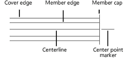
Sets the Top/Plan visibility and attributes for the structural member parts above, at, and below the cut plane. Select one or more rows, and click the applicable columns to select the desired settings. Click the Show column to toggle the visibility of the part in Top/Plan view; for the Caps rows, select which caps to show. To control appearance and visibility, select a class from the list of classes present in the drawing, or create a new class. Select <Structural Member> to place the attributes in the same class as the structural member object. Set custom pen and fill attributes, or select an option to control them by object (from the Attributes palette), by class, or, for the member and cover fills, by material (as set in the Profile tab). |
|
Center Mark |
Enter the Length of the marker and size of the Gap between the center mark and the member |
|
3D Attributes |
Sets the 3D visibility and attributes for the structural member parts. Select one or more rows, and click the applicable columns to select the desired settings. To control appearance and visibility, select a class from the list of classes present in the drawing, or create a new class. Select <Structural Member> to place the attributes in the same class as the structural member object. Click the Attributes column to set 3D attributes by object from the Attributes palette or by class; if the part uses a material (specified on the Profile tab), the fill uses the material's texture. If the part uses a material (specified on the Profile tab), the texture is initially set to the material's texture, but this can be overridden. Click the Texture column to select a texture from the Resource Selector, or click one of the buttons to use no texture, to use the class texture, or if the material's texture was previously overridden, to revert to the material's texture. |