 Adding drop points
|
Mode |
Tool |
Workspace: Tool set |
|
Modes for The Symbol Insertion tool |
Drop Point
|
Design Suite, Spotlight: ConnectCAD Cable Route ConnectCAD: Cable Route |
A drop point represents the location where cables are delivered, like a wall box, floor pocket, socket on the wall, or cables coming out of the wall. Drop points can be inserted as a stand-alone object (connect it to a cable path later), into an existing cable path, or into a wall, floor, slab, etc. Drop points can also be assigned to external connections (see Placing external connections).
A 3D equipment rack is considered to be a drop point. Stand-alone equipment can also function as drop points (see Placing equipment).
To add a drop point to the drawing:
Do one of the following:
Click the tool and one of the symbol insertion modes. Then click Drop Point Style on the Tool bar to select a resource from the Resource Selector.
Alternatively, open the Resource Manager, open the folder containing the drop points saved with the file or in the user folder, and then double-click a drop point. The tool is activated, and the Tool bar displays the Drop Point Style.
If inserting a drop point into an existing cable path, click the tool and then Insert in Cable Path mode. Then click Drop Point Style on the Tool bar to select a resource from the Resource Selector.
Click to place the object, and click again to set the rotation. If the drop point was placed into a cable path, the cable is split at the insertion point.

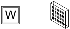
2D and 3D views of a wall pocket drop point
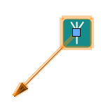
The drop point includes a handle for positioning a leader line; drag the handle to position the symbol relative to the leader line. Set the leader line endpoint from the Attributes palette.

Drop point parameters
The parameters can be edited later from the Object Info palette. Optionally, create a style resource from the object (see Creating plug-in object styles). Once added to the drawing, connect the drop point to the cable path network and connect equipment to the drop point. Drop points can also be connected to a slab object.
You can connect multiple equipment items to a drop point by selecting all of the equipment handles with the Unrestricted Interactive Scaling mode of the Selection tool enabled. Drag the handles towards the drop point.
Click to show/hide the parameters.Click to show/hide the parameters.
|
Parameter |
Description |
|
Style |
Replace, remove, or edit the current style, or create a new plug-in object style for this object. Editing a style changes all instances in the file that use the style. |
|
Hide style parameters |
Hides the parameters that are set by style; these cannot be edited from the dialog box or Object Info palette |
|
General |
|
|
Name |
Enter a name for reporting and paperwork. An automatically incrementing alphabetical name is provided by default (the letters I and O are skipped to avoid confusion with similar-looking numbers). |
|
Category |
Select a category for the type of drop point symbols available from the Symbol resource selector |
|
Connected Equipment |
Indicates the number of connected equipment items |
|
Cable Slack |
If desired, specify additional cable length for the drop point. The cable slack of the beginning and ending drop points is added to the calculated cable length of each circuit. |
|
Symbol |
Displays the currently selected symbol; select a different symbol if needed |
|
Location |
Indicates the location of the layout room, if the drop point was placed in one |

