Inserting an LED screen
|
Mode |
Tool |
Tool set |
|
Modes for The Symbol Insertion tool |
LED Screen
|
Audio/Video |

The Light-emitting Diode (LED) object simulates a variety of low-resolution LED screens in arrays on a base structure.
To insert an LED screen or array:
Click the tool and the insertion modes.
Click to place the object in the drawing, and click again to set the rotation. The first time you use the tool in a file, a properties dialog box opens. Set the default parameters. The parameters can be edited later from the Object Info palette. Some information from parameters can also be placed on the drawing using the Text Options.
Click to show/hide the parameters.Click to show/hide the parameters.
|
Parameter |
Description |
|
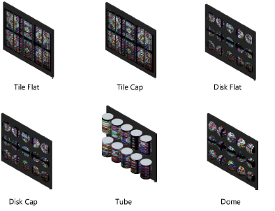
Module Shape |
Select a shape for the screen modules in the array
Tile Flat: creates rectangular-shaped modules Tile Cap: creates rectangular-shaped modules with frosted caps Disk Flat: creates round modules Disk Cap: creates round modules with frosted caps Tube: creates tube-shaped modules Dome: creates dome-shaped modules |
|
Width |
Specifies the width of each module in the array |
|
Height |
For tiled arrays, sets the height (length) of each module in the array |
|
Brand |
Specifies the screen's brand |
|
Model |
Sets the screen's model |
|
Cap Depth |
For capped arrays, sets the depth of each module's cap |
|
Tube Orientation |
For tube arrays, specifies whether the tubes are oriented vertically or horizontally |
|
Length |
For tube arrays, sets the length of one of the tube modules |
|
Build Array Based On |
|
|
Module counts and spacing |
Sets the size of the entire LED array based on the number of modules specified in the horizontal and vertical directions, as well as the horizontal and vertical spacing distance set between the modules |
|
Overall dimensions and spacing |
Sets the size of the entire LED array based on the specified array width and height, as well as the horizontal and vertical spacing between the modules; the screen count is automatically calculated |
|
Overall dimensions and module counts |
Sets the size of the entire LED array based on the specified array width and height, as well as the number of modules specified in the horizontal and vertical directions; the spacing is automatically calculated |
|
Array Width/Height |
Specifies the width and height of the entire LED array, when the array is based on overall dimensions |
|
Horizontal/Vertical Count |
Specifies the number of modules in the horizontal and vertical directions, when the array is based on the module counts |
|
Add Half Modules |
Select to add half modules to the array or none |
|
Module Total |
Displays the total calculated number of modules in the array |
|
Half-Module total |
Displays the total calculated number of half modules in the array |
|
Horizontal/Vertical Spacing |
Specifies the spacing between modules in the horizontal and vertical directions, when the array is based on spacing parameters |
|
Width/Height (Calc.) |
Displays the calculated width and height of the array, when determined by module count and spacing |
|
H/V Spacing (Calc.) |
Displays the calculated module spacing in the horizontal and vertical directions, when the array is determined by the overall dimensions and module counts |
|
H/V Count (Calc.) |
Displays the total number of modules in the horizontal and vertical directions, when the array size is determined by the overall dimensions and module spacing |
|
Pixels Per Module H/V |
Specifies the number of horizontal or vertical pixels for each module (for calculation purposes only; does not affect the module display) |
|
Array Size (Pixels) |
Displays the total number of pixels for the entire LED array |
|
Raster Information |
Specifies the raster image |
|
Array Aspect |
Specifies the aspect ratio of the array |
|
Secondary Units |
Select an additional unit of measurement to calculate the array size |
|
Array Size (Secondary Units) |
Displays the selected secondary unit of measurement for the array size |
|
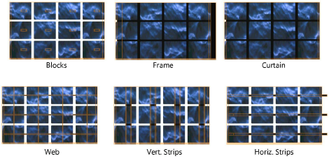
Base Structure |
Select a base structure for the array; modify the appearance of the structure by selecting Class LED Array Parts and then editing the structure class
Blocks: creates a structure of individual blocks bases for each module Frame: creates a single frame for the entire array Curtain: creates a single background for the array Web: creates a webbed structure behind the modules Vert. Strips: places the LED modules in vertical columns Horiz. Strips: places the LED modules in horizontal rows None: does not create a base structure for the array; displays only the LED modules |
|
Width |
Specifies the width of blocks, vertical or horizontal strips, or the entire frame |
|
Height |
Specifies the height of blocks, vertical or horizontal strips, or the entire frame |
|
Depth |
Specifies the depth of blocks, vertical or horizontal strips, or the entire frame |
|
Side Edge Miter |
Select the edge(s) of the outer row tiles to be mitered (none, left, right, or both)
|
|
Horizontal Inset |
Sets the horizontal distance (margin) between the horizontal edge of the base structure and the array |
|
Vertical Inset |
Sets the vertical distance (margin) between the vertical edge of the base structure and the array |
|
Pleat Width |
For curtain or web structures, specifies the pleat width of the curtain (2D only for web structures) |
|
Pleat Depth |
For curtain or web structures, specifies the pleat depth of the curtain (2D only for web structures) |
|
Webbing Width |
For web structures, sets the width of the connecting web segments |
|
Single Module Wattage/Total Array Wattage |
Enter the required wattage for a single module, and the total array wattage will be calculated; if either of these parameters are changed, the other parameter will automatically update |
|
Weights |
|
|
Reference |
Select whether to show the weight parameters for a single module or all modules |
|
Single Module |
Specifies the weight for a single module when the reference is a single module |
|
Half-Module |
Specifies the weight for a half module when the reference is a single module |
|
All Modules |
Displays the weight for all modules when the reference is for all modules |
|
Hardware |
Specifies the weight of the hardware |
|
Total |
Displays the total weight of the screen array |
|
Distributed |
Displays the distributed weight of the screen array |
|
Tilt |
Specifies the tilt angle of the screen array |
|
Simple 3D |
Creates a single textured 3D polygon to represent the screen modules; this speeds rendering when each module does not need to be shown individually |
|
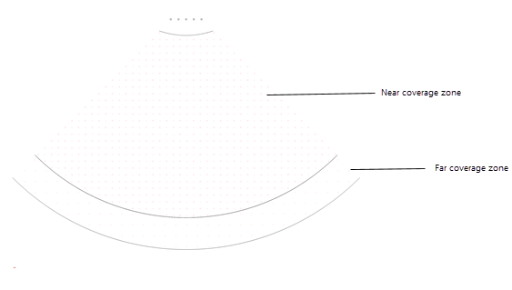
Show coverage zone (2D only) |
Indicates the viewing area based on the screen size; observers within the area should be able to see the screen
|
|
Settings |
|
|
Zone Reference |
Calculates the coverage zone based on screen width, height, or diagonal measurement |
|
Max Horiz. Angle/ Max Vert. Angle |
Indicates the maximum viewing angle of the screen, horizontally and vertically, relative to dead-on |
|
Viewing Height |
Enter the height of the average viewer when watching (likely, a seated height) |
|
Near Multiplier |
Specifies the multiplier of the reference dimension to determine the extent of the near coverage zone |
|
Far Multiplier |
Specifies the multiplier of the reference dimension to determine the extent of the far coverage zone |
|
Array Image |
Displays the name of the current screen image |
|
Edit Array Image |
Opens the Edit Aray Image dialog box; see Assigning an image, video, or input |
|
Projector 1/Projector 2 Power and Signal Details |
|
|
Circuit Number |
Indicates the circuit number where the video screen is plugged in |
|
Circuit Name |
Specifies the name of the bundled circuit group |
|
Source |
Specifies the source information |
|
Drive Line |
Indicates information about the drive line feeding the signal to the video screen |
|
Input |
Specifies the input information |
|
Frame Rate |
Specifies the frame rate information |
|
Resolution |
Specifies the resolution |
|
Location, Position, Unit, Purpose, Vendor, Cost, Note |
Adds information which can be placed on the drawing or used for reporting |
|
Row |
Enter notes about the module row, when the array is based on module counts with a horizontal/vertical count of 1 (respectively) |
|
Column |
Enter notes about the module column, when the array is based on module counts with a horizontal/vertical count of 1 (respectively) |
|
Text Options |
Opens the Text Options dialog box, to enable the display and format the text of labels |
|
Default Text Positions |
Restores text labels to their default positions |
|
Opens the Classes dialog box, to specify class naming for the various portions of the LED screen. This allows portions of the LED screen to be set to visible, grayed, or invisible. Use the standard class, select a class from the list of classes present in the drawing, or create a new class. Select <LED Screen Class> to place the LED screen element in the same class as the LED screen. Class Prefix: Specifies an optional default root class naming standard for all LED screen parts; click Assign Default Classes With Prefix to begin all LED screen class names with the prefix, so that they are sorted together. Assign Default Classes With Prefix: Sets the class names for all LED screen elements to the standard, using the Class Prefix if there is one. LED screen elements: For each portion of the LED screen, specifies the class name standard; the class names shown here are applied to the elements. |
|
|
Update |
Updates the object when changes have been made to the Object Info palette parameters |
|
Load Information |
An LED screen is considered a distributed load in Braceworks calculations; if the screen is inserted parallel to a rigging object, it is considered to be a load on that structure. Load information is used for Braceworks calculations and reports (Braceworks required). |
|
Include in calculations (Braceworks required) |
Includes the LED screen in Braceworks calculations; deselect to exclude the object from participating in structural calculations |
|
Load Group Name |
The load category is always Video for LED screen objects |
|
Load ID |
Enter a unique ID for the load for informational use in reports |
|
Load Name |
Identifies the object in load calculations |
|
Distributed Weight |
Enter the distributed weight of the LED screen object; changes here also affect the Total Weight value |
|
Total Weight |
Enter the total weight of the object |
|
Position |
Displays the name of the associated rigging object, if the LED screen is attached. For methods to attach loads, see Making the attachment. |
|
Equipment Subparts |
Lists the subparts that make up the object. These subparts are counted and reported separately in equipment and inventory lists. The parameters must be selected for display for this type of object in Spotlight preferences: Inventory pane. |
|
Equipment Virtual Parts |
Virtual parts are associated with an object and are reported in equipment and inventory lists, but do not display in the drawing. After adding virtual parts, they are listed in the Object Info palette. |
|
Edit Virtual Parts |
Opens the Virtual Parts dialog box to add virtual parts to the object; see Managing virtual parts and independent virtual parts |
|
Assign Sources |
Opens the Assign Sources dialog box to assign the object and its subparts and virtual parts to an inventory source; see Assigning equipment to an inventory |