Bending a solid or NURBS surface
|
Mode |
Tool |
Tool set |
|
Bend Solid
|
Deform
|
3D Modeling |

To bend a solid or NURBS surface:
Click the tool and mode.
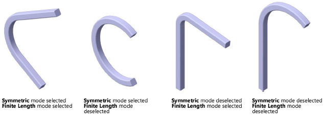
Symmetric mode is selected by default; the bend applies to both the positive and negative direction of the bend spine. If an asymmetrical bend is desired, deselect Symmetric mode on the Tool bar; the bend applies only to the positive direction of the bend spine.
Finite Length mode is selected by default; the bend applies only to the finite length of the bend spine. To bend the entire object, deselect Finite Length mode on the Tool bar.
The Symmetric mode and Finite Length mode status can also be changed at any time during the operation.
As you move the cursor over 3D objects, they are highlighted to indicate they can be modified. Click to select the solid or NURBS surface.
Shift-click to select more than one object.
A protractor feedback graphic displays around the cursor. Position the protractor on the appropriate bend spine starting point, and click.
The protractor graphic displays only when an object is selected. To position the protractor as desired, you may need to activate a specific plane using the Active Planes list from the View bar.
The protractor remains at the click point, and the protractor normal line appears. As you move the cursor, the protractor rotates and the bend spine appears; the line previews the bend spine’s end point. Click to place the bend spine.
If Finite Length mode is selected, the bend spine, which is defined by click 2 and click 3, delimits the section to bend.
As you move the cursor, the bend spine tracks the cursor, and a preview of the bent object displays.
To bend to a precise angle, press the Tab key and enter a negative or positive number in the Data bar; press Enter to display a preview of the bend.
Click to complete the operation. The result is a generic solid object.


