Creating a bulged solid or NURBS surface
|
Mode |
Tool |
Tool set |
|
Bulge Solid
|
Deform
|
3D Modeling |
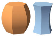
The Deform tool’s Bulge Solid mode can be used to create a convex or concave shape.

To create a bulge in a solid or NURBS surface:
Click the tool and mode.
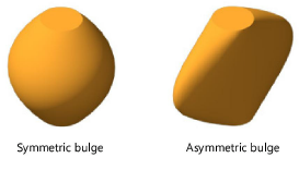
Symmetric mode is selected by default; a four-way arrow feedback graphic displays around the cursor, and an equal amount of bulge applies to both the drag direction and its perpendicular direction. If an asymmetrical bulge is desired, deselect Symmetric mode on the Tool bar; a two-way arrow feedback graphic displays, and the bulge applies only to the drag direction; its perpendicular direction has no bulge.
The Symmetric mode status can also be changed at any time during the operation.
As you move the cursor over 3D objects, they are highlighted to indicate they can be modified. Click to select the solid or NURBS surface.
Shift-click to select more than one object.
A four-way or two-way arrow feedback graphic displays around the cursor. Position the arrow graphic at the desired bulge center and click.
The arrow graphic displays only when an object is selected. To position the arrows as desired, you may need to activate a specific plane using the Active Planes list from the View bar.
The bulge center can be located away from the object being bulged.
The arrow graphic remains at the click point, and the bulge axis line appears. As you move the cursor, the arrows rotate to indicate the direction of the bulge, and the bulge reference line previews the starting point for the bulge. Click to place the reference line.
As you move the cursor, the bulge ratio line tracks the cursor, and a preview of the bulged object displays.
To create the bulge to a precise ratio, press the Tab key and enter a positive number in the Data bar. The original shape ratio is 1; numbers below 1 bulge inward, while numbers above 1 bulge outward. Press Enter to display a preview of the bulge.
Click to complete the operation. The result is a generic solid object.


